Poultry Egg Incubator with On Board Display and Humidity Maintenance

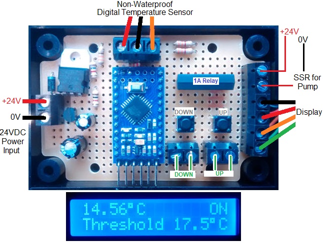
We have made many poultry egg incubators and timers over the last few years – devices which monitor and maintain temperature and humidity and also turn the eggs at regular intervals. Below is an image of one such incubator controller which we were recently commissioned to build which is a bit different from those.

poultry egg incubator controller

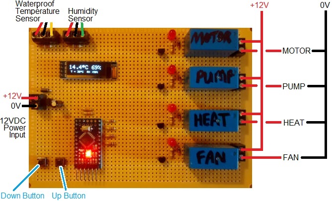
The motor is set to turn for three seconds five times per day to rotate the eggs. This is standard.

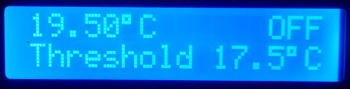
The heating element used for this incubator is a bit oversized, so we have to be careful not to overheat the eggs when it is used. When the temperature is measured to be 0.5C or more below a user set target temperature, the heater is turned on. Then, when the target temperature is reached, the heater is turned off. Because the element remains hot after being turned off, the incubator will continue to heat up to a little above target temperature while the element cools down. Therefore, there is also a fan which turns on just in case the temperature exceeds the target by 1.5C or more to cool things down long before the eggs overheat.

display for poultry egg incubation controller

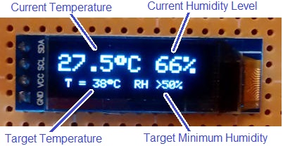
Humidity management is also achieved rather differently than usual. In all previous incubators we have made which have included humidity sensing, a commercial humidifier has been switched on/off to maintain appropriate humidity levels. For this controller, when humidity is measured to be below a user set target minimum level, a pump is turned on for five second which adds water to a container in the incubator. The rapid evaporation of this water in the warmth of the incubator increases the humidity level back above the minimum rapidly. In order to prevent flooding or raising the humidity level excessively, the controller will run the pump at most once every ten minutes.

This entire system is powered by a solar charged 12V battery bank.

If you need any type of incubator (or humidor), please email neil@reuk.co.uk with details of your requirements.

FRM01 Multifunction PLC Relay Timer Module

Pictured below is an FRM01 multi-function relay cycle timer PLC (programmable logic controller) module. FRM01 12V multifunction PLC relay timer

This small (65 x 40 mm) module offers 18 different timer functions programmable from 0.1 seconds to approximately 275 hours and used to control the on-board 10A rated relay. Some functions start automatically with power-on, others can be triggered to start (and/or repeat) with a high level pulse signal; there are delay functions, limited cycles (1-9999 repeats), and unlimited cycles.

One of the functions effectively turns this module into a latching relay board too – high pulse signal to close the relay, then another high pulse signal to open the relay.

Overall these modules are very powerful and useful in a vast range of applications requiring timer control.

Click here to buy FRM01 Timer for approximately £5 including delivery.

eBay sellers tend to offer no documentation and minimal information about these timer modules, but we have the comprehensive 8 page FRM01 User Manual (PDF 225Kb) available for download here.

Here is a video systematically demonstrating all 18 of the functions of this cycle timer

Water Tank Thermostat Controller

We were recently commissioned to design and build a thermostatic controller for a large tank of water (5m3) which has to be maintained within a narrow temperature window for the testing of ultra-sonic scanning equipment.

thermostat controller for large water tankPictured above is the device we came up with. The user can set a target temperature threshold of 15 and 30 °C in 0.5°C steps using the UP and DOWN buttons. If the temperature of the water falls to 0.25°C or more below the threshold, then a relay closes which turns on a heater. When the temperature of the water has reached 0.25°C or more above the threshold, the relay opens again and the heater turns off. This keeps the water within +/- 0.25°C of the target temperature.

Since the temperature of such a large volume of water is slow to change, the update time of the thermometer in this device does not need to be very fast. We could therefore set the resolution of the DS18B20 temperature sensor to 12-bit (0.0625°C) by accepting an almost 0.75 seconds temperature reading update time.

thermostatic controller display

The display shows the current measured temperature (top left), heater status (top right), and the temperature threshold which has been set by the user.

If you need any kind of thermostatic controller, please email neil@reuk.co.uk with details of your requirements.

Testing 128×32 OLED IIC Display with Arduino

Many of the products we sell make use of 16×2 character LCD displays. These displays coupled with an Hitachi HD44780 LCD control module enable an Arduino or Raspberry Pi to operate the display very simply with just two data connections and two power connections required.

16x2 LCD display with module for use with Arduino and Raspberry Pi

However, these displays are physically quite large being 80 x 36mm, and while they are well suited to panel mounting, they cannot really be attached to the circuit board that is driving it without creating a device with large dimensions.

We have recently being looking at alternatives to these displays looking for something physically smaller, easily circuit board mountable, lower power consumption, and improved contrast. After much testing, we have chosen the OLED display pictured below.128x32 i2c arduino displayThese displays are far smaller having an active screen area of just 22.38 x 5.58mm. They require no backlight as each of the 128×32 pixels self-illuminates thanks to OLED technology. The maximum power consumption of one of these displays is 0.08W with every pixel illuminated – therefore less when showing text or when nothing is being displayed. In all ways these displays are an improvement on the 16×2 character LCDs.

OLED display used with arduinoThese OLED displays have much better contrast than LCDs, there is more space available to display information since more characters can be displayed, and there are much better graphics capabilities with the OLED displays. The image above shows the new OLED version of the LCD display from our REUK Low Voltage Disconnect with Display pictured below.

LCD display on REUK low voltage disconnect (LVD)

The biggest advantage however is the ease with which these OLED displays can be mounted to the circuit boards of our controllers so that we can produce more convenient small form factor integrated units with no increase in our pricing for customers.

arduino pro mini controlled 128 x 32 oled display

If you are interested in trying out one of these displays for your own projects, click here: buy 128×32 OLED Display for under £3 including delivery. If you intend to use one with an Arduino project, you will need to add the following libraries to your Arduino IDE: SSD1306 Library and Adafruit GFX Library, so that you can communicate with the display.

Controller for Multi-Pump Irrigation System Water Distribution

Pictured below is a diagram of an irrigation system comprising three water tanks located on three terraces. The lowest tank contains a bilge pump which will pump water up to the next terrace, and the tank on that terrace has a pump to send water up to the top tank.
Irrigation system diagram - multi tank, multi pump, multi terrace

The bilge pump has its own float switches and will, when powered, start pumping when its upper float switch detects water (full tank) and will stop when its lower float switch does not detect water (empty tank).

The two higher tanks have float switches so that their water level status can be monitored. Pictured below is the controller we built to manage the two pumps in order to best distribute the stored water across the three tanks while minimising overflow wastage. Ideally no tank should ever be completely empty, and no tank should be full and overflowing if the next higher tank is not full.

irrigation system pump controllerThis controller, built around an Arduino Pro Mini monitors the status of the float switches of the two upper tanks to decide when power should be supplied to a pump or pumps. If for example the middle tank is full, and the top tank is not, the Tank 2 pump will be run until either the middle tank is empty or the top tank is full. If the bottom tank is full, and Tank 2 is not, then the bilge pump will fill up Tank 2.

In order to prevent multi-switching (a pump being turned on and off rapidly and repeatedly) timers are built into this controller so that a pump will always overrun by 10 seconds when it is to be turned off. This will ensure that the state of the float switch which called for the pump to be turned off will be stable and unaffected by turbulence in tank.

If you need any type of pump controller, please email neil@reuk.co.uk with details of your requirements.