Automatic Irrigation System with Moisture Probes

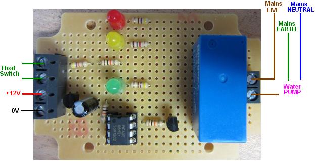
Pictured below is a controller we recently made to automate watering of plants depending on the moisture level of the soil in which they are growing.

Automatic irrigation controller with moisture sensing probes

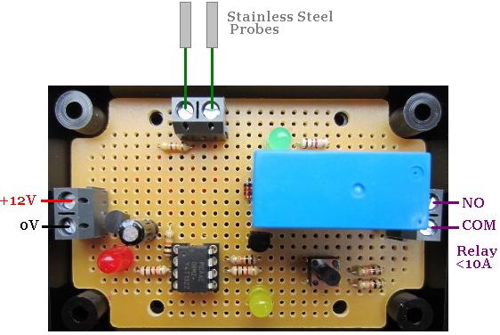
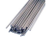
This device measures the resistance between two stainless steel probes made from 1.6mm arc welding rods (pictured below) to which leads have been soldered, and inserted into the soil a few centimetres apart. When the soil is measured to be ‘dry’, a pump is turned on which waters the soil. When the soil is subsequently measured to be ‘wet’, the pump is turned off, but only if it has already run for a user programmable number of minutes first.

Stainless steel welding rods used as moisture sensors

To provide default wet and dry thresholds, the resistance between the probes was measured at what the user considered to be the dry and the wet threshold. These values were 36.5 kOhms or lower for wet, and 229 kOhms or higher for dry (with the probes inserted 7cm into the soil, 6cm apart). Therefore we programmed the controller to turn on the pump after 5 continuous seconds of resistance measured to be below 36.5 kOhms, and turn off after 5 continuous second of resistance measured to be above 229 kOhms.

Since different growing mediums may be used in the future, we also made this controller so that the user can calibrate the wet and dry thresholds themselves or revert to the default values.  Calibration is achieved simply by putting the probes into soil which the user considers to be at the wet or dry threshold, and pressing a button to save the measured resistance value in memory as the new threshold.

If you need an irrigation controller similar to this, please email neil@reuk.co.uk with details of your exact requirements.

Rainwater Pump Controller – Anti-Interference Modifications

Pictured below is one of our rainwater toilet flush pump controller units which we have had to modify to overcome a problem with interference.

rainwater toilet pump controller programmed to cope with interference in long float switch cablesThe customer had a problem with the original unit we supplied due to the length of the cables running to the float switch in the header tank – more than 10 metres. This controller is designed to check the status of a float switch at the top of a header tank every two hours. If the header tank is found to not be full then the pump is turned on until it is full, pumping water from a water butt at ground level up to the header tank which gravity feeds the toilets.

The way we had programmed the original unit, the float switch had to remain high on the full water level continuously for one second before the pump would be switched off. Unfortunately during that one second of multiple measurements, at least one measurement was getting scrambled by interference resulting in the pump staying on continuously.

For the new modified unit, the controller tests the status of the float switch 10 times every half a second, and if more than seven of those readings are high, the controller will turn off the pump.

There are ways that we could have suppressed the interference problem with modifications to the hardware, but as we could not test the controller on site we chose a software method which we have found to work well previously – particularly in Eastern and Southern Europe where they seem to have more interference problems than here in the UK.

Project of the Day – Automatic Toilet Flush Counter

This week we have been working on a project for a toilet manufacturer making a device which will count and log the number of times a toilet is flushed or partially flushed.

Although flow meters are already in place to measure the exact volume of water consumed by the toilets being tested, the key metric to calculate accurately is the amount of water used per flush, and to obtain that information it is essential to also count the number of times the toilet has been flushed.

There is no easy direct way to detect whether a full or partial flush has occurred, so two float switches have to be inserted into the toilet cistern – one just below the full cistern depth and the other just above the cistern depth immediately after a full flush.

automatic counter to log and display the number of times a toilet is flushed

When the level of water in the cistern drops below full (indicated by the upper float switch going low), we know that a flush has begun. Typically a full flush will take around 5-10 seconds at most to empty the cistern into the bowl (at which point the lower float switch will go low). Our system waits for up to 15 seconds to see if a flush is a full flush. If during that time the lower of the two float switches does not go low, it knows that a partial flush occurred.

This flush is then added to the relevant counter – full or partial – and displayed. The system then waits for the cistern to fill up again, and when upper float switch goes high it re-arms the flush detector ready to detect the next flush.