In our articles Use Thermostat as 12 Volt Timer and Convert Thermostat to 12V Timer Switch we looked at how a cheap battery powered programmable thermostat could be converted for use as a timer relay switch. This system works very well and there are now many people around the UK and rest of the world doing exactly that for Solar Powered Poultry Lighting and other applications for which commercial 12V timer switches proved too expensive.
The one disadvantage is that the thermostat is powered by two AAA batteries. Rechargeable batteries can of course be used, but their self-discharge rate does make them ideally suited to this application. In cold weather they are likely to need recharging in 6-8 weeks which is annoying. Disposable alkaline batteries are recommended, but they have a heavy environmental impact and will still need replacing every 6 months to one year.
When used in a 12 Volt system – for example, solar panels charging a lead acid battery or battery bank, it is relatively simple to modify these thermostats yet further by adding a small 12V-to-3V voltage regulator and replacing the AAA battery bay with suitable leads or a connector.
12V to 3V Voltage Regulator
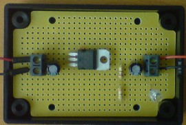
In our articles LM317T Voltage Regulator and Using the LM317 to Regulate Voltage we present a simple circuit which can be used to provide a regulated output voltage. Two resistors* are used to fix the output voltage from the circuit, and a capacitor (e.g. 100uF) is used to keep the output voltage free from spikes.
* In our experimentation we used R1 = 270 Ohms and R2 = 390 Ohms to obtain a measured output voltage of 3.03 Volts. Read the above linked articles for more information.
NEW A simpler (and physically far smaller) alternative to the LM317T is a 3.3V voltage regulator. We used the LE33CZ* which provides a reliable 3.30V output from an input voltage of 3.5 to 20+ Volts, and a maximum output current of 100mA – easily enough to power the timer thermostat. This regulator can be used for many other low current 2xAA/AAA battery powered devices.
* Click here to download and view the LE33CZ Datasheet (26 page PDF) .
Converting the Thermostat
As usual we were working with the Towerstat RSP thermostat since we offer these at a reduced price in the REUK Shop: click to buy Towerstat RSP now.
The battery contacts are very inaccessible being as they are located deep within the battery bay, and so it is necessary to disassemble the thermostat. Fortunately this is a very simple process.
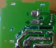
First of all pop the front cover off the unit following the instructions in the printed user guide. The main display and circuit board can then be lifted up and out of the case (as shown below) by squeezing each of the four white plastic catches in turn inwards while pulling gently upwards.
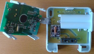
The top of the battery bay is now clearly visible together with the three small screws which hold it in place. Unscrew these three screws and keep them and the battery bay cover somewhere safe. Although you will no longer be using batteries, the battery bay fixings physically hold the relay board to the case, and so must be replaced when the modification is complete.
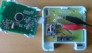
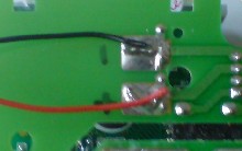
As shown above, the two battery contacts will now be exposed. In the image, two crocodile leads are shown attached to the contacts). Since we will not be soldering leads onto these contacts directly, they should be removed to ensure that they will never short-circuit.
The wires used to make these spring contacts are surprisingly difficult to cut, so it is easier just to stretch the springs so you can access the point at which they enter the circuit board, and then wiggle them to and fro a few times until metal fatigue causes them to snap clean off.
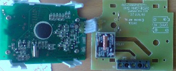
Flipping over the relay board, two large soldered contacts are visible (see image below). It is to these contacts that you will solder your positive and negative leads. Note that the polarity is printed clearly on the board next to where you snapped off the contact springs. We marked the contacts on the underside of the board with a + and a – to ensure we made no mistakes when we came to solder.
Now you have the simple job of soldering insulated leads onto the positive and negative contacts. Use a lot of solder to ensure a reliable strong connection and then start the process of reassembling* the thermostat unit.
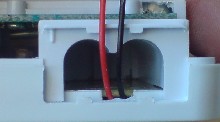
* As the leads will run along the underside of the relay board, it is a good idea to cut a small piece out of the plastic at the entrance of the battery bay so that the wires can emerge without being crushed by the refitted board and similarly to ensure that everything clicks back together straight and true. See image below:
When you connect the leads emerging from the thermostat to your 3 Volt DC source, the thermostat display should come on, and the unit should work just as it did when it was battery powered. While testing, you can of course use a couple of AAA or AA batteries * in a suitable battery holder to power the thermostat.
* AA batteries typically have 2-3 times the storage capacity of AAA batteries, and so if you have a problem with your 12V power source, a couple of AA batteries will power the thermostat 2-3 times longer than was possible with AAA batteries fitted inside the unit.
2009 Update – ECO ET2 Themostat
We are now using the ECO ET2 programmable room thermostat for these applications as we no longer have a supplier for the Towerstat RSP. (The instruction manual for the ET2 can be downloaded here as a PDF: ECO ET2 Thermostat User Instructions.)
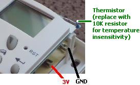
Converting the ECO ET2 to be powered from a 12V source (via a 3V voltage regulator) is easier than was the case with the Towerstat RSP since it is not so difficult to access the points onto which cables need to be soldered. These points are pictured and labelled above, and though you cannot see it in the photograph, they are helpfully labelled with 3V and GND on the circuit board itself.
Buy a Ready Converted Thermostat
If you do not want to undertake this work yourself, we are very happy to do it for you at a nominal charge and supply you with a one of our 12V-to-3V regulators so that you can power your thermostat/timer directly from your renewable system charged 12V battery or battery bank. Please contact neil@reuk.co.uk with details of your exact requirements.