Testing 128×32 OLED IIC Display with Arduino

Many of the products we sell make use of 16×2 character LCD displays. These displays coupled with an Hitachi HD44780 LCD control module enable an Arduino or Raspberry Pi to operate the display very simply with just two data connections and two power connections required.

16x2 LCD display with module for use with Arduino and Raspberry Pi

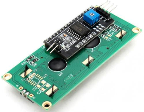
However, these displays are physically quite large being 80 x 36mm, and while they are well suited to panel mounting, they cannot really be attached to the circuit board that is driving it without creating a device with large dimensions.

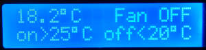
We have recently being looking at alternatives to these displays looking for something physically smaller, easily circuit board mountable, lower power consumption, and improved contrast. After much testing, we have chosen the OLED display pictured below.128x32 i2c arduino display
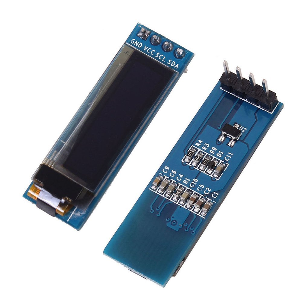
These displays are far smaller having an active screen area of just 22.38 x 5.58mm. They require no backlight as each of the 128×32 pixels self-illuminates thanks to OLED technology. The maximum power consumption of one of these displays is 0.08W with every pixel illuminated – therefore less when showing text or when nothing is being displayed. In all ways these displays are an improvement on the 16×2 character LCDs.

OLED display used with arduino
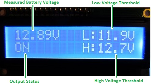
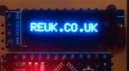
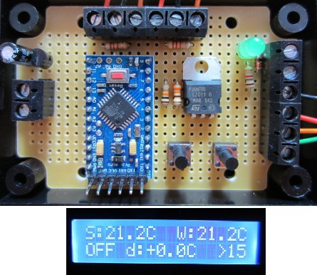
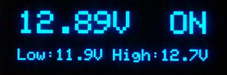
These OLED displays have much better contrast than LCDs, there is more space available to display information since more characters can be displayed, and there are much better graphics capabilities with the OLED displays. The image above shows the new OLED version of the LCD display from our REUK Low Voltage Disconnect with Display pictured below.

LCD display on REUK low voltage disconnect (LVD)

The biggest advantage however is the ease with which these OLED displays can be mounted to the circuit boards of our controllers so that we can produce more convenient small form factor integrated units with no increase in our pricing for customers.

arduino pro mini controlled 128 x 32 oled display

If you are interested in trying out one of these displays for your own projects, click here: buy 128×32 OLED Display for under £3 including delivery. If you intend to use one with an Arduino project, you will need to add the following libraries to your Arduino IDE: SSD1306 Library and Adafruit GFX Library, so that you can communicate with the display.

Controller for Multi-Pump Irrigation System Water Distribution

Pictured below is a diagram of an irrigation system comprising three water tanks located on three terraces. The lowest tank contains a bilge pump which will pump water up to the next terrace, and the tank on that terrace has a pump to send water up to the top tank.
Irrigation system diagram - multi tank, multi pump, multi terrace

The bilge pump has its own float switches and will, when powered, start pumping when its upper float switch detects water (full tank) and will stop when its lower float switch does not detect water (empty tank).

The two higher tanks have float switches so that their water level status can be monitored. Pictured below is the controller we built to manage the two pumps in order to best distribute the stored water across the three tanks while minimising overflow wastage. Ideally no tank should ever be completely empty, and no tank should be full and overflowing if the next higher tank is not full.

irrigation system pump controllerThis controller, built around an Arduino Pro Mini monitors the status of the float switches of the two upper tanks to decide when power should be supplied to a pump or pumps. If for example the middle tank is full, and the top tank is not, the Tank 2 pump will be run until either the middle tank is empty or the top tank is full. If the bottom tank is full, and Tank 2 is not, then the bilge pump will fill up Tank 2.

In order to prevent multi-switching (a pump being turned on and off rapidly and repeatedly) timers are built into this controller so that a pump will always overrun by 10 seconds when it is to be turned off. This will ensure that the state of the float switch which called for the pump to be turned off will be stable and unaffected by turbulence in tank.

If you need any type of pump controller, please email neil@reuk.co.uk with details of your requirements.

Controller for Heater used to Prevent Condensation on Telescope Mirror

A common problem for amateur astronomers is condensation forming on the mirror in their telescopes. During the night the mirror cools down, and then in the morning as the air warms up, condensation forms on the mirror which is colder than the surrounding air. The same thing happens to the surface of a bottle when you take it out of a fridge, but for a telescope it is problematic as condensation deteriorates the reflective coating on the mirror, and of course a foggy coating reduces the quality of the star images obtained by the telescope.

One solution to this problem is to warm up the mirror so that it remains 2 to 5 degrees Celcius above the ambient air temperature – something which can be achieved using a heating element and a thermostatic controller. If the mirror gets too cold, it will be covered in condensation. If the mirror gets too hot, it could warp. Therefore accurate control of the heating element is essential.

telescope condensation prevention controller with heater

Pictured above is one such thermostatic controller we recently prepared for a customer loosely based around our 2013 Solar Water Heating Pump Controller.

This device has two ds18b20 digital temperature sensors – one which attaches behind the mirror of the telescope and the other which measures the ambient air temperature. When the temperature at the mirror falls to within 2°C (or any other user programmable value) warmer than ambient, the heating element is switched on (via the onboard relay). The heating element stays on until the mirror has heated up to be at least 5°C (or any other user programmable value) warmer than ambient.

We used a non-waterproof sensor at the back of the mirror as this area remains dry and that sensor needs to respond to quick temperature changes. (The protection on waterproof temperature sensors slows down their response to temperature change.) We did however use a waterproof sensor to measure ambient air temperatures because that sensor is exposed and ambient air temperatures change relatively slowly.

The heating cycle continues automatically ensuring condensation does not form on the mirror, and the mirror is not over heated. This is a 12VDC powered controller managing a 12VDC heating element so that it can be battery powered when used at remote locations.

If you need a user programmable thermostatic controller for your telescope heating element, please email neil@reuk.co.uk with details of your requirements.

Target Shooting Lights Controlling Timer

Pictured below is a timer for use in competitive target shooting. Usually we make turning target controllers which turn the target to face and away from the shooter at the required times. This controller instead is for use with a fixed target, using a red and a green light to tell the shooter when to shoot.

shooting target lighting controllerThe red light starts off on. The start/stop button is pressed and the range master gives a vocal command for shooters to load. After 30 seconds, the red light turns off and the green light turns on – shooting commences. After a user programmable timer period has elapsed, the red light turns on again, the green light turns off, and shooting stops.

With this particular controller, the available timing options are fixed as 4, 6, 8, 10, 20, or 150 seconds. The timer option button is used to cycle through those options with red indicator LEDs used to show which option is currently selected. (We also make timers like these with a physical display and the ability for the user to change the values of the timing options instead of having a fixed selection – see here for details of some of our other shooting timers.)

The type of bulb to be used with controller is pictured below: a low current 12VDC powered 22ds LED bulb from Onpow.22ds 12vdc LED bulbIf you need any type of shooting range timer, please email neil@reuk.co.uk with details of your requirements.

Conservatory Cooling Fan Controller

We sell a wide range of types of differential temperature controllers which are primarily used in solar hot water systems. However, with slight modifications, they can also be put to good use in other scenarios.

thermostat for conservatory coolingPictured above is an Arduino Pro Mini based fan controller we made for use in conservatories and other sunny rooms to help to keep the temperature from getting too hot.

This device can be used to turn on an extractor fan when the temperature in the room gets above a user set value, and keep it on until the room temperature has fallen below a second user set value. By dumping excess hot air from the room, the room’s temperature can be kept in a comfortable range.

display for conservatory cooling fan controller

In the photograph of the device’s display above, the air temperature is showbn to be measured as 18.2C. The fan (which is currently off) will turn on when the air temperature goes over 25C, and then turn off again when the air temperature falls below 20C.

We have also previously made these types of thermostatic controllers to automatically drive hot air from a sunny conservatory into cooler regions of the house. An insulated conservatory can still get very hot even in the winter months, so sending the hot air to the cooler side of the house is an easy and cheap way to reduce heating bills.

12V Low Voltage Disconnect with Display and SD Card Datalogger

12V low voltage disconnect with display and sd card dataloggerPictured above is a low voltage disconnect device which we recently made for a client. It offers all of the battery monitoring, protecting, and datalogging functions and features of our REUK Programmable Low Voltage Disconnect with Display and Datalogger, but with the added benefit of an on board microSD card to store the measured battery voltage once per minute.

low voltage disconnect sd card datalogger

The voltage data is written to a simple text file on the SD card. When the battery is connected to the low voltage disconnect and powers it, POWER CONNECTED is written to the log file. Then each subsequent minute, the battery voltage is written to the file preceded by the number of minutes since the power was last connected. For example the line 6,13.98 indicates that 6 minutes after the power was connected, the battery voltage was measured to be 13.98V.

While the pre-existing basic datalogging of the LVD is useful for constantly displaying the minimum, maximum, and average measured voltages, every now and then it is good to have the option to copy the data from the SD card to a PC for more detailed analysis and plotting etc.

If you need any kind of datalogger, please email neil@reuk.co.uk with details of your requirements.

Solar Water Heating Pump Controller for Distant Pool

Pictured below is our standard 2016 Solar Water Heating Pump Controller with Datalogger. We recently made a modified version of this controller for use in a particular situation where the standard unit would not be very efficient.

2016 SOLAR PUMP CONTROLLER WITH LCD DISPLAY AND DATALOGGER. Solar water heating pump controller with backlit display to show temperatures and system status information and a datalogger
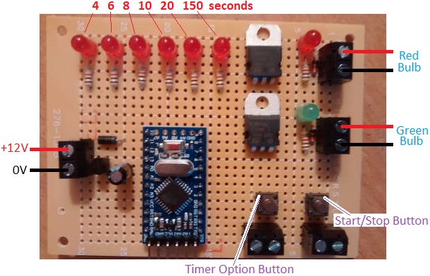
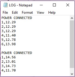
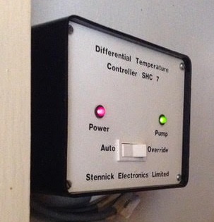
In this case, the controller was to be used to heat a swimming pool. The problem was that this pool was located 30 metres away from a garage where the controller would be fitted, with 50mm water pipes already installed running underground to and from the pool from the garage (on the roof of which were installed solar water heating panels). There was therefore no easy way to retro fit a temperature sensor at the pool – that would necessitate digging a new 30 metre long trench, fitting sensor cable into an armoured tube, and burying it.

It was however possible to fit a temperature sensor to the return water pipe where it emerged in the garage, but the contents of that pipe would cool down much faster than the large volume of water in the pool, and this would result in the pump being turned on frequently unnecessarily, often cooling the pool instead of heating it.

To get around this problem, the controller was modified to provide additional features. The key feature was that the pump would not be turned on until the temperature of the solar panel exceeded a user programmable value. When this threshold is reached, the pump is run for a user programmable number of seconds (TD) which circulates the water through the system sufficiently to get an accurate measurement of the temperature of the pool water. When TD seconds have elapsed, if the temperature differential between the solar panel and pool exceeds the user programmed differential (diffOFF), the pump will continue to run until the differential falls below diffOFF – standard operation for the 2016 controller.

If however after the test run of the pump, the differential is not high enough, the pump will be turned off, and the temperature of the pool sensor will be saved. For up to the next four hours this saved value of the pool temperature will be used rather than the sensor temperature (which will rapidly fall when the pump is turned off). The pool temperature over the course of 4 hours will not fall by more than a degree or two, so using this saved value is acceptable for efficiency. During the 4 hours, if the temperature differential exceeds the second user programmed differential (diffON), the pump will be run as per standard operation and after TD seconds the controller will start to use the current pool temperature sensor measurement instead of the previously saved value as the pipe in the garage will now be at pool temperature. The pump will continue to run until the differential falls below diffOFF.

If during the 4 hours, diffON is not achieved, the controller will wait until the solar panel temperature exceeds the user programmed temperature before running the pump for TD seconds again and repeating the above processes.

Overall these modifications (together with a few additional features not described above) will result in a far more efficient system than our standard controller would have given and less wear on the pump.

If you have any special requirements which are not met by our standard controllers, please email neil@reuk.co.uk with details.

Replacing 30 Year Old Solar Hot Water Controller

Pictured below is the differential temperature controller fitted to a 1980’s solar hot water system. After many years of successful operation, this controller finally failed (pump stays on all the time) and needed to be replaced.

Old solar water heating pump controllerSomething functionally identical was required, at least externally for the benefit of the user, so we were tasked to build a differential controller with relay to switch a mains powered pump, and to include a power on LED indicator, a pump on LED indicator, and a physical switch to select between standard automatic operation and ‘override’ which forces the pump to run.

Circuitry found in 1980's differential temperature pump controller

The internals of the old controller are pictured above. It shows a simple system with mains power going in and coming out again on its way to the pump switched by a relay, a transformer to get low voltage DC from the incoming mains AC, a potentiometer which is probably there for the installer to set the temperature differential required between solar panel and hot water tank for the pump to be turned on or to zero the measured difference when the sensors are at the same temperature, and the connections (two core) for two temperature sensors which are almost certainly going to be thermistor type sensors. There is also an IC visible which will most likely is a microcontroller, a 555 timer, or a comparator.

The sensor leads (and all other leads) were soldered in place upon installation, and the sensor cables were run through walls and are therefore inaccessible. Since the existing cables were 2-core, we had to build the new controller using sensors with two connections – LM335 – rather than the 3 connection digital sensors we use in most of our controllers – DS18B20 temperature sensors.

Our 2013 Solar Water Heating Pump Controller is the most similar unit we sell to this existing controller, so used that as the foundation of the controller we built.

modified 2013 solar water heating pump controllerAll LEDs, buttons, and switches have to be external to the controller board, so these have extended leads which connect via screw in terminals. We supplied a plug in 12VDC power supply rather than fitting a transformer directly to the circuit board, and we added an LED which turns on when the unit is powered, and the override switch which can be used to force the pump to run. We fitted the programming button (used to set the temperature differentials at which the pump turns on and turns off) to the circuit board, but connected terminals in parallel with it so that an external button can be panel mounted now or at a later date.

If you need a modified version of one of our differential temperature controllers, please email neil@reuk.co.uk with details of your requirements.

Animal Feeder Motor Controller with Timer

Pictured below is a motor controller we made recently for an automatic animal feeder system.

Animal feeder motor controller with timerThe feeder itself has two buckets on a belt which is connected to a 12VDC motor. When the motor is run, the buckets scoop up feed from a container and drop it into a trough for the animals. If the motor is left running, more and more feed will be scooped up and added to the trough, so a controller was required to ensure that each time the motor was run, the correct amount of feed was deposited in the trough reliably.

The motor needs to run for less than one minute each time, therefore a 12V programmable digital timer was chosen. The user can programme the timer to turn ON for one minute at the exact times of day that the animals are to be fed.
A switch was added to the mechanical setup which closes each time the buckets have completed one full revolution – i.e. picked up and deposited feed.

The central controller waits for the timer to turn ON. Then it turns on the motor, and keeps it running until it detects the mechanical switch closing indicating that the feed buckets have been through one rotation.
When the timer next turns ON, the switch status is ignored for the first couple of seconds (since it remains closed until the motor has moved the buckets around a bit), and then the controller keeps the motor running until the switch closes again…another feed complete. This automatic feeder will keep the animals fed the right amount at the right times of day for as long as there is feed left to be scooped up.

If you need any kind of timer or motor controller, email neil@reuk.co.uk with details of your requirements.

Poultry Egg Incubator with Humidity Sensor

Pictured below is a controller we recently made for use in a poultry egg incubator, designed to keep eggs within a very narrow specific temperature and humidity range for a few weeks. This is achieved using a heater, a fan, and a humidifier.egg incubator with humidity sensor, fan, heater, and humidifierThe eggs need to be turned at least three times per day every day except for the last few days before hatching. Previously we made a Controller for Poultry Incubator which had a motor which was turned on and off at different times of the day to turn the eggs. For this new incubator, the motor used is a very slow turning 12 VAC device makes 6 full rotations every 24 hours. That motor therefore did not need to be controlled with a timer – it is just left running at all times.

egg incubator controller status summary displayThe display for this controller shows the current measured temperature from the waterproof DS18B20 digital temperature sensor (read at 12 bit resolution = 0.0625°C resolution), and the humidity from a DHT11 sensor (within 5% accuracy). The DHT11 actually has a built in thermistor, but its temperature measurements are nowhere nearly accurate enough for this type of project.

The bottom line of the display shows the three devices being controlled – heater, fan, and humidifier respectively. In the image above, the heater is marked as being on. If the humidity level gets too low, the humidifier will be switched on. If the temperature gets too hot, the fan will turn on (and of course the heater will already be turned off by then).

Setting humidity range for poultry egg incubator

The user has full control over the thresholds at which the heater, fan, and humidifier will turn on and turn off. The temperature thresholds for the heater and fan can be set in steps of 0.2°C, and the humidity thresholds in steps of 2%.

For example, the heater could be set to turn on at or below 36.4°C and off again at or above 38.4°C. Then the fan could be set to turn on at or above 38.6°C and off again at or below 37.4°C. Humidity should ideally be around 60% (raising to 65% just before hatching), so the humidifier could be set to turn on at or below 56% and off again at or above 64% relative humidity.

display for egg incubatorWith all the thresholds programmed in by the user according to the requirements of the particular type of eggs to be incubated, a button can be pressed to show in turn the values programmed in – for example, above the humidifier is shown to be set to turn on at or below 43% RH and turn off at or above 70% RH.

Feb 2020 – We have now released the full Arduino sketch (source code) for this device here: http://www.reuk.co.uk/wordpress/full-arduino-code-for-poultry-egg-incubator-with-humidity-sensor/

If you need any kind of egg incubator controller (or the electronics for a temperature and humidity controlled humidor – functionally pretty much identical to an incubator!) – please email neil@reuk.co.uk with details of your specific requirements.