In this article we will look at how a simple system using float switches and relays can be put together to automate the process of getting water from a well, spring, or stream into a header tank ready for use. This system design uses no electronics, is very cheap and simple to put together, and it is reliable in operation.
In our article Simple Sump Pump Controller we put together an electronics-free system toautomatically pump out a sump pit when it gets full. One float switch at the top of the pit detects when it is full (turning on the pump), and a second near the bottom detects when it has been emptied (turning off the pump). If you have not already done so, you may wish to read that article first so you understand the concept behind the system described here.
Well Pump Control System Design
To automatically fill a header tank from a well, we need to reverse the configuration of the sump pit emptying system so that a float switch at the bottom of the header tank detects when it is empty starting the pump, and then a float switch at the top of the tank detects when the tank is full stopping the pump.
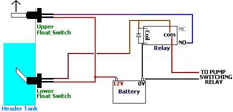
Pictured above is the connection diagram for this modified system. The float switches are configured such that they sit horizontally when they are not in water, and float upwards when they are in water: in water = switch open, out of water = switch closed.
When the water level in the header tank falls below the lower float switch (LFS), that switch closesenergising the relay. Since the upper float switch (UFS) must also be out of water and closed, the following connection is made:
Therefore, the relay is latched – i.e. will remain energised – for as long as the UFS remains closed (which it will as long as it is not under water). When the level of the water pumped up from the well finally reaches up above the UFS, it opens that switch breaking the connection between the battery and the relay coil and so turns off the pump.
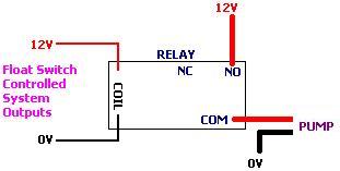
Connecting the Pump
A 12V pump is connected to his system via a second relay as pictured below:
If a mains powered pump is to be used, then a qualified electrician must do the wiring (or at least check it and sign it off) and ensure that everything is correctly earthed and insulated etc.
Well Pump Control Circuit Board
Pictured below is an example circuit board for this system. Three LEDs (and electronics) have been added for visual confirmation of system status – red lit when the header tank is full, yellow lit when there is water in the header tank, and green lit when the pump is on.
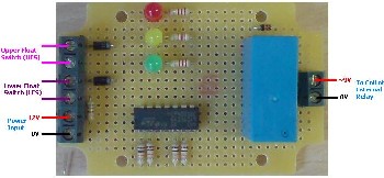
Note that adding the LEDs made this circuit more complicated since it quite difficult to make an LED light up when a switch is open (which the float switches are when they are under water). In the circuit pictured above a 4001B quad NOR gate integrated circuit was used to control the LEDs.
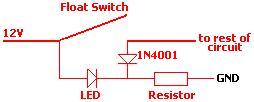
NEW Pictured below is our latest circuit design for this system which gets rid of the need for an integrated circuit making it easier to solder together.
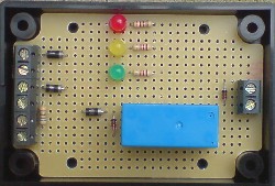
This version uses the mini-circuit pictured below to turn the red and yellow LEDs on only when the relevant float switch is open. When the float switch is closed, the voltage on the positive and negative legs of the LED is 12V – therefore the LED is off. When the float switch is open, 12V is on the positive leg of the LED and the negative leg is connected to GND (0V) via a current limiting resistor – therefore the LED is lit.
If you would like to have a pump controller such as the one pictured above put together, please contactneil@reuk.co.uk with full details of your requirements. Our latest circuit is available for around £17.
Other Uses for this System
This simple system is ideally suited for use with irrigation, rainwater collection, and rainwater toilet flush projects. In any situation in which a tank or cistern has to be automatically filled so it never runs dry, this design can be used.