Arduino Thermostat with Full Code

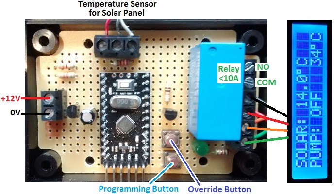
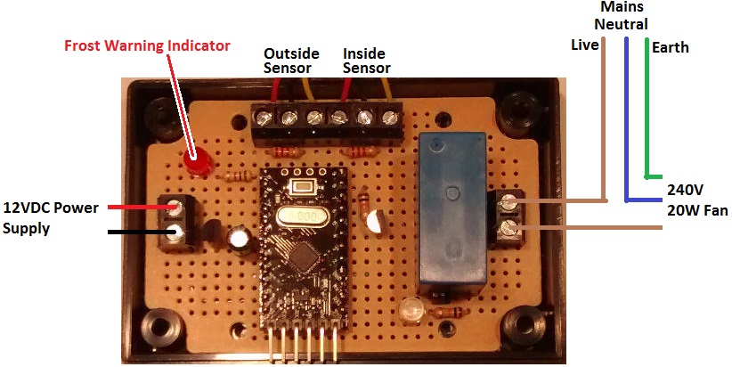
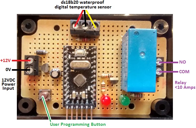
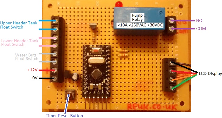
We are often requested to build simple thermostats – devices to turn something on or off depending on a measured temperature. Pictured below is an example of one such thermostat we made recently using an Arduino Pro Mini.

arduino thermostat

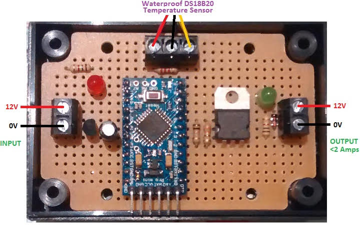
This particular thermostat was designed to keep a 12V 2A output turned on unless the temperature measured on a waterproof DS18B20 digital temperature sensor reaches above 80°C. The output must then remain off until the measured temperature has fallen to below 70°C.

The thermostat was designed to control a low voltage pump, turning it off if the water in a hot water tank fed by a solar water heating panel gets to be too hot. The 10°C temperature difference between the turn off and turn back on temperatures is hysteresis to prevent the pump being turned on and off rapidly multiple times.

In the image above a MOSFET is used to switch the small pump on and off, but typically a relay would be used in most pump controlling thermostats so that high currents and high voltages can be switched by the low voltage powered thermostat. Therefore, in the Arduino sketch, all references are to a relay. The relay will need to be connected to the relevant Arduino pin via an NPN transistor.

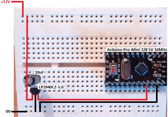
Here is a poorly drawn and badly photographed circuit diagram of the thermostatic relay controller. Click on the image to view it in larger size.

circuit diagram for arduino thermostat relay controller

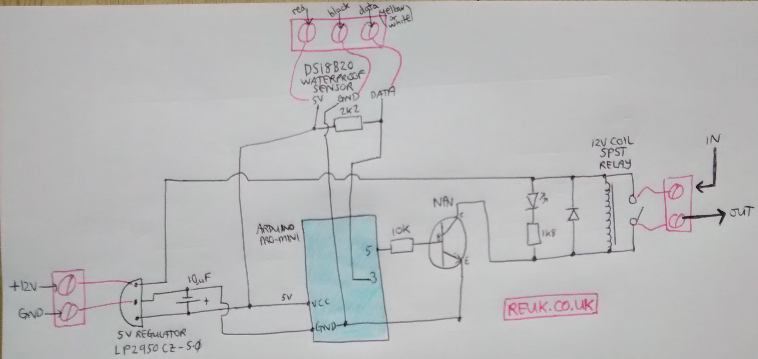
We used an Arduino Pro Mini because of its small size and price, but any Arduino board could be used for this type of controller.

While the Arduino Pro Mini has an on board 5V regulator, we prefer to use an external low drop 5V regulator (lp2950cz-5.0) because they are much more robust and will cope with higher input voltages – for example 12V batteries while they are being heavily charged.

The red LED shown on the circuit board at the top of this page is not used in this project.

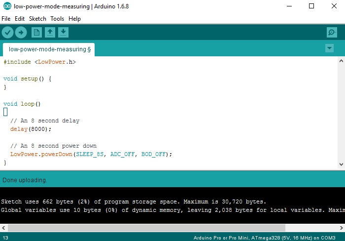
Here is the full sketch (source code) for this thermostat

/*
 * REUK.co.uk - 2017
 * This is a thermostat which will keep a relay closed
 * until the temperature measured reaches 80 degrees C, and then will then
 * then re-close the relay only when the temperature falls to 70 degres or below.
 */

// For the temperature sensors
#include <OneWire.h>
#include <DallasTemperature.h>
// Data wire plugged into pin 3 on the arduino
#define ONE_WIRE_BUS 3

// Setup a oneWire instance to communicate with any OneWire devices (not just Maxim/Dallas temperature ICs)
OneWire oneWire(ONE_WIRE_BUS);

// Pass our oneWire reference to Dallas Temperature. 
DallasTemperature sensor1(&oneWire);

const int relay = 5;

// Fixed temperature thresholds - turn off output at >80C, and turn back on again when <70C
const float onTemp = 70.0;
const float offTemp = 80.0;

// Keep track of whether the relay is energised/closed (1) or open (0). Start with closed (1).
int relayStatus = 1;

void setup(void)
{ 
 // Start up the library
 sensor1.begin();
 //set the resolution to 10 bit ADC
 sensor1.setResolution(10);
 
 // Set up the relay output for the arduino, and start with it high
 // since the thermostat only turns off at >offTemp degrees.
 pinMode(relay, OUTPUT);
 digitalWrite(relay, HIGH);
}

void loop(void)
{ 
 // Read in the temperature of the sensor
 sensor1.requestTemperatures(); // Read temperature of sensor1
 float sensorOneTemperature = sensor1.getTempCByIndex(0);

if(relayStatus == 1 and sensorOneTemperature >= offTemp-0.00001){
 // Relay is currently closed, but the temperature exceeds offTemp - therefore open the relay
 digitalWrite(relay, LOW);
 // Remember the new status
 relayStatus = 0;
 }

if(relayStatus == 0 and sensorOneTemperature <= onTemp+0.00001){
 // Relay is currently open from a previous high temperature event, but now the temperature 
 // is below the threshold so close it again
 digitalWrite(relay, HIGH);
 // Remember the new status
 relayStatus = 1;
 }

// Wait 1/10th of a second before we measure the temperature again.
 delay(100);
}

Hen House Door Controller for Dawn/Dusk or Timer Operation

Pictured below is a controller we recently made to open and close the door of a hen house automatically.

hen house door controller with light detector for dawn/dusk operation and a programmable digital timerWe make a lot of door controllers for a range of different needs, and in general they either open and close the door depending on times programmed into a timer, or automatically detect dawn and dusk with a light detector and open or close the door accordingly.

With this particular controller, the user can select between two modes – dawn/dusk mode or timer mode. If timer mode is selected, the door will open when the timer turns ON and close when the timer turns OFF. In this way the door can be made to open and close at times convenient to the owner – for example opening the door later on weekend mornings so that the poultry do not disturb neighbours.

If instead the dawn/dusk mode is selected, the door will open at dawn and close at dusk, with the ambient light level for the day-dusk and night-dawn thresholds calibrated by the user when setting up the controller and light detector in its location.

If you need any kind of automatic door controller, email neil@reuk.co.uk with details of your specific requirements.

Solar Swimming Pool Heating Controller with Datalogger and Display

Our 2016 Solar Water Heating Pump Controller is one of our most popular products. Pictured below is a derivative recently requested by one of our clients.solar pump controller for swimming pool heating with datalogger and lcd displayThis controller will be used to control the operation of a pump circulating water through a solar thermal panel. Our standard controllers have at least two sensors – one for the pool/tank and one for the solar panel – but for this particular project only one sensor could be used: at the solar panel.

Therefore, instead of using the temperature differential between the solar panel and the pool to decide when the pump should be turned on or off, the user sets a high temperature threshold above which the pump will turn on, and a low temperature threshold below which it will subsequently turn off.

Sensible starter values would be 70 degrees C at the panel to turn on the pump, and around below 35-40 degrees at the panel to turn off the pump. With experimentation and analysis (this device has a built in datalogger) it will be possible to refine these thresholds to maximise efficiency. The pump should not be turning on and off too frequently and running for very short times, but the panel should also not be left at very high temperatures for a long time or it will radiate heat away before it can be transferred to the water.

If this device was to be used in a small pool or hot tub, and if the arriving hot water from the panel is pumped straight in without pre-mixing, a lower pump turn on temperature would be essential so that no-one gets burned on the incoming hot water.

If you need any kind of pump controller, email neil@reuk.co.uk with details of your specific requirements.

Turning Shooting Target Controller

Pictured below is a controller we recently made to control a shooting target for competitive shooting.target-turning-timer-crowleBased around an Arduino Pro Mini, this device is used to edge or face a shooting target according to preset and user-set timings.

Display for a shooting target controller

By default, the target is edge on to the shooter. When the start button is pressed, a relay closes which turns the target face on to the shooter. An accurate timer then starts and counts down the number of seconds the shooter has until the target is turned edge on again.

There are five preset modes – 165 seconds, 35s, 8s, 4s, and 2s. There is also a sixth mode which the user can programme to be any duration from 1 to 999 seconds.

Buttons are fitted to the circuit board, but there are also connectors to which external buttons can be connected so that the device can be fitted in a box with just the two external buttons and display visible.

If you need any kind of shooting target controller, please email neil@reuk.co.uk with details of your requirements.

Apple Store Fan Thermostat

Pictured below is a device we recently made to act as a fan controller for an apple storage room.apple store fan controlling thermostatThis device has two waterproof DS18B20 temperature sensors connected to it and a relay to switch the power to a fan which drives air from outside the apple store to the inside.

Whenever the outside temperature is measured to be a couple of degrees cooler than the inside temperature, the fan is turned on to drive the cooler air into the store. When the temperature differential falls to zero – i.e. the inside and outside temperatures are equal or the inside is cooler, the fan is turned off again.

This device also has built in frost protection to prevent freezing air from being blown into the apple store. If the outside temperature falls below 2 degrees C, the fan is turned off if it is on, and remains off until the outside temperature has increased by a couple of degrees.

If you need any kind of thermostat, email neil@reuk.co.uk with details of your requirements.

Programmable Automatic Plant Propagator Thermostat

In our March 2015 blog post Automatic Plant Propagator Thermostat, we showed a device we had made to automatically turn on/off 12V heat pads under young plants to prevent them from getting too cold (or hot).

This device connected the power to the heat pads when the measured temperature was below 17 degrees and off again when it had got back up to 23 degrees.

Different plants require different temperature ranges, so in order to meet those demands, we created the device pictured below.

programmable automatic plant propagator thermostatThis device has been enhanced with a user programming button enabling the user to set the low temperature threshold at or below which heating pads should be turned on, and also the number of degrees of temperature increase which must occur before the heating pads are turned off again. This gives a far more flexible thermostat for a wide range of plant propagation.

If you need a thermostat like this or similar for plant propagation thermostat, email neil@reuk.co.uk with details of your specific requirements.

Automatic Dawn Dusk Gate Opener

24v dawn dusk gate controller openerPictured above is a controller we made recently for a gate which is to be opened at dawn and closed at dusk automatically.

The controller is based around our standard REUK Dawn Dusk Relay Controller which uses a light detector and user calibration to detect the arrivals of dawn and dusk depending on measured ambient lighting levels.

This particular unit is designed to control a large gate motor which requires two contacts on its electronics to be shorted out (connected together) for one second to toggle the state of the gate – i.e. open the gate if it is closed, or close it if it is open.

When dawn is detected, the on board relay closes for one second which opens the gate. Then, when dusk is detected, the relay closes again for one second which closes the gate. The controller has a selection of timers and automation logic built in which prevent false dawns and false dusks being detected when there are clouds moving across the sun early and late in the day.

If you need any kind of dawn/dusk detecting controller, email neil@reuk.co.uk with details of your requirements.

Irrigation Pump Timer with Low Voltage Disconnect

Pictured below is a device we made to control the pump of an automatic and often unattended irrigation system which is solar powered.

irrigation system pump control timer with low voltage disconnectprogrammable digital timer is set with the times that the pump is to be run – typically very early in the morning and in the evening. The pump for this particular irrigation system is relatively high powered, so could not be switched directly by the timer. Therefore a 10A rated relay is built into the controller.

As this system is solar powered and also often left unattended, it was essential to include a low voltage disconnect which will automatically prevent the pump from running whenever the measured battery voltage is found to be <11.9V. It then waits until the battery has been charged back up to over 12.5V before allowing the pump to run again.

LED indicators are included to show when the programmable timer is ON, the status of the low voltage disconnect, and also the status of the pump switching relay.

If you need any kind of irrigation pump timer or controller please email neil@reuk.co.uk with details of your requirements.

Rainwater Toilet Pump Controller with Display and Timer

Pictured below is a rainwater toilet pump controller which is different from those we usually make.

Rainwater toilet pump controller with display to show cumulative minutes that the pump has run.It is designed for a standard system which has two float switches in the header tank (one near the top and one near the bottom) as well as a float switch near the bottom of the water butt to prevent the pump running when there is no water to pump.

This particular controller also has a display which shows the status of the float switches and system status, and also has a built in timer which stores and displays the cumulative duration for which the pump has been running.

Display for rainwater toilet pump controller to show status and cumulative pump run time.With this timing information, and knowing the flow rate of the pump used, it is possible to easily calculate the volume of rainwater which has been supplied to the toilets and therefore how much mains water (and therefore money) has been saved with the system.

If you need any type of rainwater toilet system pump controller email neil@reuk.co.uk with details of your specific requirements.

Testing Arduino Low Power Library with Pro Mini

In general when using an Arduino Pro Mini in one of our projects or products, we use an external LP2940CZ-5.0 voltage regulator instead of the on board regulator. This is because most things we make are for 12V battery systems, and the voltage from a 12V battery can get to well over 12V which is the specified upper input voltage for a Pro Mini. We have measured that one of these regulators with a 10uF capacitor across its 5.0V output, draws a quiescent current of only 0.079mA.

We have found that an Arduino Pro Mini, whether powered as described above, or with the on board regulator draws around 20mA @ 12.0V. This is very high for an always on battery powered device – it will use 500mAh (0.5Ah) of battery charge per day. Therefore, we are always interested in testing ways to minimise power consumption.

breadboard test of low power library for arduino pro mini

We set up the above test circuit with a 12V input, and our usual LM2940CT-5.0 regulator connected to an Arduino Pro Mini (16MHz / 5V). With a sketch containing just delay(8000); in the loop() function – i.e. the Arduino will wait 8 seconds, then wait another 8 seconds, then wait another 8 seconds, etc – we measured a current draw of 19.793mA @ 12.0V input voltage.

We downloaded and installed the following Lightweight low power library for Arduino – LowPower.h, and modified our test sketch as shown below to power down the microcontroller for 8 seconds within the loop.

arduino-pro-mini-low-power-testing

This time we measured the current draw to be just 6.265mA @ 12.0V input voltage – a huge reduction of around 70% power consumption obtainable just by replacing the delay function with the powerDown function from the LowPower library.

We make a lot of dataloggers and monitoring devices which spend most of their time doing nothing – just waiting to take the next measurement. Therefore this low power library is a quick and easy way to reduce power consumption.

(Note that 8 seconds is the maximum power down duration that can be set with this library, but by using loops of multiple 8 second intervals in your sketches, you can create a low power consumption delay of as long as you want.)

A standalone arduino in a low power consumption circuitIf you use a Standalone Arduino on a breadboard directly powered by a battery pack of the correct voltage (i.e. no voltage regulation required), it is possible to run your Arduino off less than 50uA @5V (<1000th the power consumption of our tests above) and therefore power something for years with a AA cells or smaller. See here for an excellent article How to Run An Arduino For Years on a Battery from the Open Home Automation website where they use the JeeLib low power library with a standalone Arduino.