Programmable Target Shooting Timer Relay Board

Target shooting relay timer controller with display

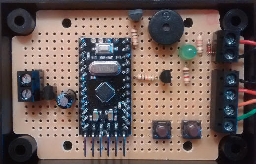
Pictured above is a target shooting timer relay controller with programmable options for different shooting programmes. With this device the user can set the number of seconds that the target is to remain edge-on to the shooter and how many second that it is to remain face-on to the shooter, and also how many cycles of edge and face the shoot will comprise.

Target shooting timer display

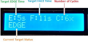
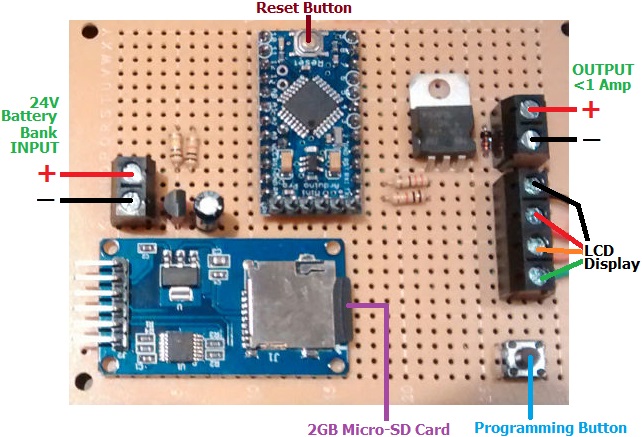
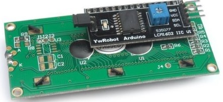
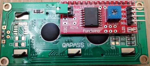
The backlit display with this device shows the user programmed number of seconds that the target will edge (E) then face (F), and the number of cycles (C) for which it will be repeated. It also shows the current status of the target.

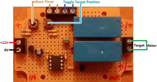
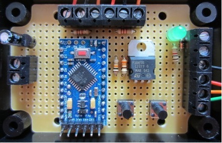
There are two buttons on the controller. The MANUAL button is used to enter the programming mode to set the timings for the programme and also to toggle the target manually between facing and edging. The AUTO button is used to start the programme. The programme starts by edging the target, and finishes also with the target edged.

target shooting timer relay display in action

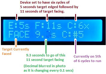
While the shooting programme is running, the display continues to show the user set programme values and the status of the target. It also shows a running countdown of the time remaining during this part of the cycle, and also which cycle the shooter is currently on.

If you need any kind of automated user-programmable timer for target shooting, please email neil@reuk.co.uk with details of your requirements.

Shooting Timer Instructions

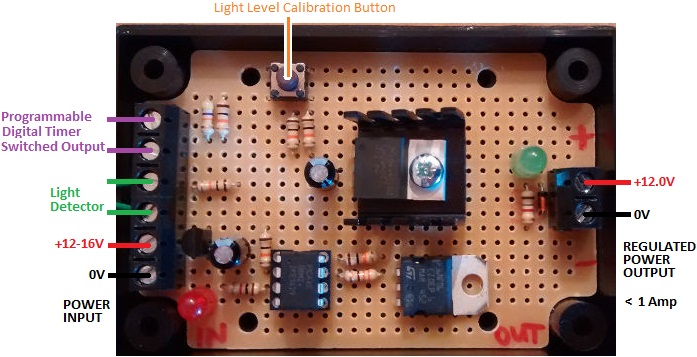
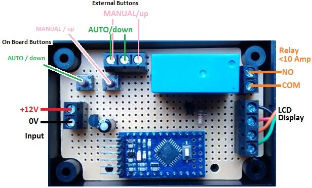
Connect up the timer as shown in the connection diagram at the top of page making sure to use correct polarity for the 12VDC power input. The controller has buttons on board, but external push to make buttons can be connected in parallel to those as shown in the connection diagram.

Programming

To set the timings for your controller, press and hold the UP button for a couple of seconds until the display shows PROGRAMMING MODE. When you release the button, you will be prompted to ‘SET Edge time’. You can use the UP and DOWN buttons to change the displayed value within the range 1-99 seconds. Five seconds after you last pressed a button, whatever is displayed for Edge is saved in memory, and you will be prompted to ‘SET Face time’. Again the UP and DOWN buttons are used to change the displayed value within the range 1-999 seconds. (Since the face time can be set to a high value, if you press and hold the UP or DOWN button, you will be able to speedily increase or decrease the value.) Finally you will be prompted to ‘SET Cycles’. This can be set within the range 1-9 repeating cycles of the Edge/Face times.

The values you set in programming mode are saved in long term memory and are therefore retained if/when you disconnect and subsequently reconnect the power to the controller. You only need to repeat the above described steps if you want to change one or more of the saved values.

Using the Timer

In normal operation with your timings already programmed, the Manual/UP button can be used to manually toggle the position of the target. If the target is face on, press the button, and it will edge. Press the button again, and the target will be face on again.

The relay on the controller is closed when the target is edge on, and open when the target is face on. Therefore, when no power is being supplied to the target, it is expected that your target will be configured to be face on.

To run the timer, press the Auto/DOWN button. All cycles start with the target edge on, so if you have manually set the target to be face on, it will turn to edge on. As shown above, the display will show where you are in the programme, the countdown timer, the target status (edge or face), and which cycle you are currently on.

If you want to stop the timer when it is running, press the Auto/DOWN button again. The target will turn to be edge on if it is not already.

New Raspberry Pi Zero On Sale

Raspberry Pi ZeroPictured above is the new Raspberry Pi Zero available for just US$5 or £4.

This stripped down Raspberry Pi is the lowest power consumption version yet at just 160mA or lower at 5VDC.

It has one micro USB connection for power input, and one for connection to peripherals such as a USB hub (for connection of a keyboard and mouse etc) or for a WiFi dongle for headless applications.

The standard Raspberry Pi HDMI port has been replaced with a mini-HDMI port, there is no ethernet, no composite video (although headers are supplied), and even the 40 pin GPIO header is not supplied.

As with the more recent Raspberry Pi models, a micro-SD card port is fitted for you to load your operating system of choice.

The Raspberry Pi Zero has a single-core BCM2835 processor overclocked to 1GHz, and 512MB of on board RAM. This offers three times the performance of the original Raspberry Pi at less than one-quarter the price.

The price of the Raspberry Pi Zero is so low that it competes with even the cheapest Arduino clones, even when the cost of a micro-SD card and GPIO headers is included. It is still more power hungry than an Arduino, but offers much more functionality than any Arduino board.

Raspberry Pi Zero is half the size of the already diminutive Raspberry Pi A+ coming in at a tiny 65mm x 30mm x 5mm and weighing just 9g.

Raspberry Pi cable adapters and GPIO headers

Pictured above is a bundle on offer comprising the GPIO headers, a micro-USB adapter and mini-HDMI adapter offered for £4 at the Raspberry Pi Swag Store. With this bundle or equivalent, you can connect your Raspberry Pi Zero to a television with a standard HDMI cable and plug in a standard USB hub.

User Programmable Countdown Timer with Display

Pictured below is a programmable timer we recently made for animal behaviour research. The operator switches on the power to the timer which turns on an LED bulb (to indicate that animal training is in progress). When the timer finishes its count down the bulb is turned off, and an on board buzzer sounds briefly to remind the operator to turn off the power to the timer.

Programmable digital timer for animal behaviour research

This timer is built around an Arduino Pro Mini board with additional components. Using the on board up and down buttons and a 16x LCD digital display, the operator can set the timer in one minute intervals to the desired time.

The most recent setting is stored in long term memory, so the timer only has to be re-programmed if the operator wants it to run for a different time than that most recently used.

LCD display for animal behaviour timer

While the timer is running, the timer setting and the time to go countdown are both displayed as shown above.

As the built in timer in an Arduino is consistent, but not very accurate, this device had to be calibrated to ensure that it was running at the correct rate. Initially it was programmed with 1000 Arduino milliseconds set to correspond to one actual second and run for 20 (Arduino) minutes simultaneously with an accurate stopwatch. When the timer finished, the stopwatch was stopped and compared to what the Arduino considered to be 20 minutes. It turned out that the Arduino clock was slow by 13 seconds over the 20 minutes, so we divided the real 20m13s by 20m and multiplied this error factor (1.0108) by 1000ms to give 1011 as the number of Arduino milliseconds in one actual second. After updating the code on the Arduino to reflect this, the timer ran to accuracy of under 1 second over 20 minutes – fine for a timer to be used typically for 10 minutes or less.

If you need a timer for any application, email neil@reuk.co.uk with details of your exact requirements.

hen house lighting controller with digital timer and light detector

Pictured below is a new hen house lighting controller we recently made.

hen house lighting controller with programmable digital timer and light detector overrideThis device is designed to controller artificial lighting in hen and other poultry housing to trick the birds into thinking it is summer even during the winter so that their egg yield is kept high throughout the year. It is based around our REUK Poultry Lighting System but with a few modifications.

This particular version makes use of both a light detector and a programmable digital timer. The user sets the timer to turn ON before dawn and turn OFF after dusk. During the hours of darkness between the timer turning ON and dawn, and then between dusk and timer turning OFF, the artificial lights are turned on. The output from this device passes through a low-drop 12V regulator to protect LED bulbs from excessive voltage.

With the timer turned ON for 15 hours per day (e.g. from 4am to 7pm), the level of light in the hen house will be optimised for the birds’ laying; and the light detector prevents the artificial lighting being on when not necessary (due to ambient lighting) which reduces the cost and size of the solar panel and battery used to power the system.

If you need any type of automatic poultry lighting or door opening controller, email neil@reuk.co.uk with details of your exact requirements.

Air Pistol Shooting Target Controller

Pictured below is a controller we recently made for competitive air pistol shooting training.

Shooting Target ControllerOn the shooting range there is a target connected to a motor. If the motor is powered for one second with one polarity, the target will turn to face the shooter. If the motor is powered for one second with reverse polarity, the target will turn edge on to the shooter. (Click here to see how we reverse the polarity of a motor with two relays – alternatively, we could have used an H Bridge motor controller.)

The controller has two buttons, and also screw in terminals so that external buttons can be added in parallel if the controller is to be enclosed. One button is used to toggle the target position – to edge it when it is facing, and to face it when it is edge on. The second button is used to start the training routine.

When the start timer button is pressed, the target will be turned edge on to the shooter. Then after seven seconds, the target will be turned to face the shooter for three seconds. This edge for seven seconds face for three seconds is repeated five times, and then the target is edged to wait for the next shooter.

If you need any kind of automatic timer controller board, email neil@reuk.co.uk with details of your requirements.

12V Low Voltage Disconnect with Warning Buzzer

Pictured below is a 12V low voltage disconnect circuit with a low battery warning buzzer.

Low voltage disconnect with warning buzzer sirenWe sell a wide range of low voltage disconnect circuits in the REUK Shop as well as producing many bespoke LVDs on request. This particular circuit is based around our standard user programmable mini 12V low voltage disconnect, but enhanced to have a buzzer which sounds for one minute when the low voltage disconnect is triggered by 10 continuous seconds of low voltage measured on the battery. This warns the user that they need to take measures to recharge the battery.

There is also a switch on the circuit board so that the buzzer function can be turned off when not desired/required.

If you need any kind of low voltage disconnect, please email neil@reuk.co.uk with details of your requirements.

Time Lapse Photography Controller

Pictured below is a time lapse photography controller we recently made for a customer who is using it at a remote site.

Automatic programmable time lapse camera controllerRather than leaving the camera and MiFi (mobile Wi-Fi hotspot) constantly powered (necessitating a large battery), this controller turns them on only when they are needed – first MiFi is turned on, then 45 seconds later the camera is turned on, and then a further 15 seconds later a relay tiggers the camera shutter to take the photograph. The camera and MiFi are then left on for a further three minutes (so that the photograph can be processed by the camera and uploaded).

A programming button is provided which enables the photographer to take one shot every 5, 10, 15, 20, or 25 minutes etc, and once set up, this controller will run autonomously indefinitely, taking photographs at the required time interval and uploading them to the cloud server.

If you need a time lapse camera or similar timer controller, please email neil@reuk.co.uk with details of your exact requirements.

24V Low Voltage Disconnect with SD Card Datalogger

Pictured below is a low voltage disconnect device we recently made for use with a 24V battery system. In addition to the user-programmable low voltage disconnect functionality and LCD display of our standard Programmable 12V LVD with Display, this modified 24V device also includes a full datalogger, storing measured battery voltages at regular intervals to a micro-SD card for later analysis.

24V Low Voltage Disconnect with SD Card DataloggerThis particular unit is destined to be used by a company specialising in the maintenance of the UK’s transport infrastructure; with the low voltage disconnect used to protect batteries from being overly depleted, and the datalogger used to track the rise and fall of battery voltage over time.

If you need any kind of low voltage disconnect and/or datalogging solution, please email neil@reuk.co.uk with details of your requirements.

i2c Address Problems with eBay 16×2 LCD Modules

arduino i2c 16x2 LCD display module

At REUK we use a lot of 16×2 LCD display modules of the type pictured above (and available here: 16×2 LCD Arduino Module  from just £3) for some of the products we sell in the REUK Shop and more often in our bespoke products.

These units have a standard Hitachi HD44780 compatible 16 x 2 character liquid crystal display (LCD) to which is pre-soldered a small controller board (in the pictured example from YwRobot) enabling [i2c] communication between the LCD and an Arduino or Raspberry Pi over just two wires (plus two more wires for the power inputs). In the case of the Arduino, pin A4 connects to SDA on the module and pin A5 to SCL.  Many Arduino libraries (e.g. LiquidCrystal_I2C) are available which have typically made these LCDs very simple to set up and use even for beginners.

In all of the example code for these libraries, the default address on the i2c bus for these LCDs is always given as 0x27, and so after years of using them, and it always being correct, it just became automatic to expect it to be true.

Funduino Arduino LCD display module

However recently (since April 2015) the small modules on the backs of the available displays have suddenly changed from being red (Funduino – pictured above) to being black (YwRobot) – probably because the YwRobot modules are cheaper than the Funduino units.

In general, the YwRobot modules work identically to the old Funduino units with one key difference. We have found that approximately one unit in five (including from different suppliers) is not preset with 0x27 as its address meaning that we have had to modify our long established, tried and tested Arduino code to get them to work.

In the most part we have (after some research) found that the address 0x3F works with these units, but we have also had a few units for which neither 0x27 nor 0x3F works. In those cases we have to use the i2c scanner sketch to find out what the address is for each particular display which is a pain. The main problem is that almost none of these units are supplied with any accompanying documentation, and those that do always state 0x27.

If you have had similar problems, please email neil@reuk.co.uk with details of the address you have discovered for the display(s) you purchased and the source of the display(s) so that we can build up a comprehensive reference document to help people who have purchased a display and have no idea of its address. The consistent 0x27 addressed Funduino units are getting harder to source and don’t seem to be coming out of China any more.

Heating Circuit Pump Controller

Pictured below is a controller we recently made for a wood fire cooker based heating circuit.

heating circuit pump controllerThe controller itself is physically identical to our standard 2014 Solar Water Heating Pump controller with an LCD to display temperatures and system status and a couple of ds18b20 digital temperature sensors. However, it has been completely re-programmed for an alternative use.

The customer has an Esse wood fired cooker with a 2.5kW domestic water circuit. This thermosyphon water heating circuit feeds a 140 litre thermal store in which a heat exchanger is used to heat up domestic hot water.

As there is some surplus heat over domestic hot water requirements, a pump is required to divert surplus heat to a panel radiator situated below the tank.

Two temperature sensors are to be fitted – one in the middle of the storage tank and the other on the return thermosyphon flow to the cooker.

The controller we put together for this system measures the temperature of the two sensors, and if both are found to be above user set values (for example, 80C for the tank and 45°C for the return flow), then the pump will be turned on to divert hot water to the radiator. When either of the two sensor temperature subsequently drops 2°C or more below the set values, the pump will be turned off sending hot water back into the storage tank.

If you need any type of water heating system controller, email neil@reuk.co.uk with details of your exact requirements.