Testing Accuracy of micro:bit Internal Clock

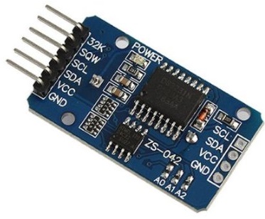
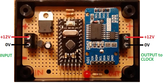
At REUK.co.uk we make a lot of timers for a wide range of different applications. Most projects only call for a timer to be accurate to within around 10 seconds per hour. For those that require greater accuracy, we sometimes use a real time clock such as the DS3231, and other times (when the microcontroller we are using is inaccurate but CONSISTENTLY inaccurate) we just calibrate the timer against a previously tested and known accurate timer.

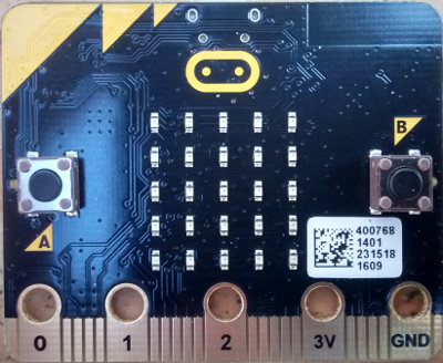
While having a first play around with MicroPython on the micro:bit, we ran a few one minute tests of the accuracy of the internal clock. When hand timing with a stopwatch we consistently found that one micro:bit minute was actually around 59.85 seconds. That is of course very close to the 60.00 seconds of a true minute and the error could well have been due to human error with the stopwatch, but it did appear that our micro:bit was running a little fast (since its ‘minute’ was finishing quicker than a true minute). Being 0.15 seconds fast every minute may not sound a lot, but it equates to the internal clock being minutes fast per day. Had the timing appeared to be a tiny bit slow, it could just have been that there was a delay due to the time taken for the micro:bit to do internal processing etc, but as the timings appeared to be fast, they must actually be fast.

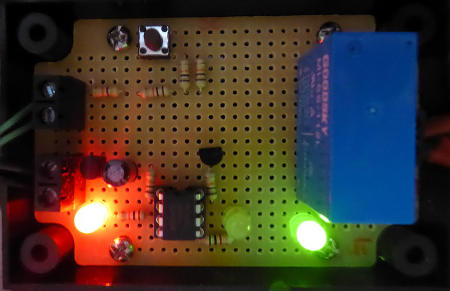
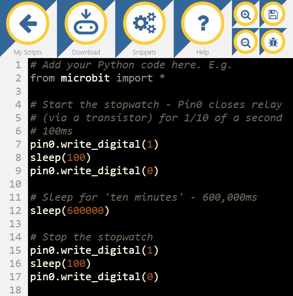
In order to test this properly, we connected a relay via a transistor to one of the digital output pins of the micro:bit. The NO and COM terminals of this relay were in turn connected in parallel across the contacts of the start/stop button on a previously cannibalised stopwatch. We then wrote a small MicroPython script to briefly set the output pin to digital HIGH to start the stop watch, and then after 10 minutes sleep(600000) – i.e. sleep for 600,000 milliseconds, 600 seconds, 10 minutes – again briefly set the pin high to stop the stopwatch.

testing the micro:bit internal clock accuracy

Running this test ten times and averaging the results we found that the micro:bit ten minutes was actually 9 minutes, 58.51 seconds (598.51 seconds instead of 600.00). The timings were very consistent with the shortest and longest measured times both being just 0.03 seconds away from the average – a tight range of 9m58.48s to 9m58.54s measured over the ten ten minute periods.

Looking at the average time, 9 minutes 58.51 seconds is 0.248% faster than 10 minutes. Being 0.248% fast is not a big deal when timing events lasting seconds or a couple of minutes, but over the course of a 24 hour period, our micro:bit would gain 215 seconds, or over 3.5 minutes which is not insignificant.

The consistency we had found in the inaccuracy was a very good sign. It made manual calibration of our micro:bit a possibility so that we would forever know (at least if timing accuracy is not significantly affected by changes in ambient temperature or input voltage) that this particular micro:bit’s clock could be trusted without the need for an external real time clock (RTC).

The Python command we used to get the micro:bit to sleep for one second was sleep(1000). Apparently with our micro:bit this resulted in it sleeping for a little less than one true second, therefore we needed to increase the sleep time by the 0.248% that the internal clock was now known to be fast. It would be nice to use the command sleep(1002.4833), but unfortunately it is only possible to use a whole number (integer) value – i.e. sleep(1002) or sleep(1003). Either of these approximations would make times measured by our micro:bit 5 times more accurate, but that is still around 45 seconds too fast per 24 hours – not good enough.

Therefore, when we want to time long intervals – hours and days – we need to sleep for longer intervals such as sleep(601489.98) corresponding to 10 minutes to increase the accuracy possible. Luckily enough 601489.98 is almost exactly 601490 micro:bit measured milliseconds. So, in any projects which require us to measure long time periods with our micro:bit, we will count the number of our pre-calibrated 10 minute intervals have passed measured with sleep(601490). Now calibrated, our micro:bit should certainly be accurate enough for a wide range of future long duration projects.

The timing accuracy we found for our micro:bit before calibration was 25 ppm (parts per million) which compares favourably with the typical 50 ppm found with Arduino boards, and we found the consistency in timing inaccuracy to be better with micro:bit than we have previously found with Arduino. However, we could have been lucky or unlucky with our particular micro:bit board. We will need to repeat our experimentation with multiple micro:bits to find the typical timing accuracy of micro:bits in general in the future.

micro:bit Battery Capacity

In our recent blog post: micro:bit Power Consumption, we look at how much power the micro:bit draws at different input voltages while idle, illuminating the full array of 25 LEDs, or with the processor operating at 100% load carrying out calculations. In this post, we will look at how this power consumption relates to battery life.

The micro:bit is supplied with a 2xAAA battery holder. Assuming that the majority of users will put a pair of good quality alkaline cells into this battery holder for powering their micro:bit projects, we will use 3 Volts as the input voltage in the calculations to follow. Good alkaline cells start off at just over 1.5 Volts and maintain this voltage until it begins to drop off only when the cells are almost depleted of charge. (The calculations would be quite different if rechargeable NiMH cells were to be used for example since with an input voltage of 2.4-2.5V, the power consumption is notably lower.)

Referring to the table of power consumption results (available in the post linked to at the top of this post), with 3 Volts on the input we saw the following:

microbit power consumption with a 3V input voltagei.e. at idle (minimal processing and no LEDs on), power consumption is just 5.83mW, but with the processor working at 100% and all of the LEDs on, power consumption is over 43mW.

Good quality AAA cells typical hold a charge of somewhere from 800-1000mAh, AA cells from 1800-2400mAh. There are higher capacity cells available, but these are usually optimised for use with digital cameras and similar supplying high current briefly each time a picture is taken rather than the steady state constant low current typical for a micro:bit project. They also tend to be much more expensive.

battery life testing with micro:bitThe table above takes the power consumption data previously measured with a 3 Volt input voltage and shows for how many days the battery pack will last for a wide selection of different capacities. For example, if you had a processor intensive project which made use of all or nearly all of the LEDs at once, and a pair of 1000mAh Duracell Plus AAA cells, you could expect to get approximately 3 days of battery life. If on the other hand you had a project which was not processor intensive, did not make use of the LEDs, and used a pair of 2400mAh AA cells, you could expect around 50 days of battery life.

There are many factors above which will affect the real world battery life including the ambient temperature, the specific features of the project to be built, and of course any additional components, sensors, or devices to be powered at the same time as the micro:bit. However, it will hopefully give you a pretty accurate idea of what to expect and to inform your choices when you are choosing how to power your project.

Bookmark microbit.me.uk to view all our previous and future micro:bit related articles.

micro:bit Power Consumption

Having finally managed to obtain a micro:bit, the first thing we wanted to test was the power consumption at different input voltages.

The micro:bit is supplied as a kit together with a 2xAAA battery holder which plugs into the micro:bit, two cheap generic AAA cells, and a USB cable for connecting the micro:bit to a PC to upload your code to it (and which can also be used to power the micro:bit via the onboard voltage regulator).

The input voltage for micro:bit is labelled as 3 Volts. Alkaline AAA cells such as those offered by Duracell supply around 1.5-1.7 Volts each when fully charged. Rechargeable NiMH cells, something around 1.25 Volts. Therefore, since the micro:bit is designed to be battery powered by TWO AAA cells, it must be able to operate reliably from a wide range of input voltage – e.g. just 2V from a pair of depleted rechargeable NiMH cells, up to at least 3.4V to cope with a pair of brand new out of the box Duracell cells.

In order to test power consumption, we used the Microsoft Block Editor (available for use at the official micro:bit website) to build a simple project as shown below. Click on the image to see it in full size.

Power testing the micro:bit

This will first turn off all of the LEDs in the 25 LED array so the micro:bit is not doing anything apart from background processing. If the A button on the micro:bit is then pressed, all LEDs will light up and remain on for five seconds. If the B button is pressed, the processor of the micro:bit will be worked hard by generating 233,000 random numbers. (The reason that 233,000 was chosen was that it took the micro:bit 10 seconds to complete that many iterations of the loop, and that gave the time necessary to reliably measure the minimum and maximum current drawn by the micro:bit while under this heavy load).

Powering the micro:bit from a variable DC power supply starting down at 1.5V, the voltage was increased until it was sufficient to have the LEDs turn on. We found this voltage to be at around 1.80V. We then tested different input voltages from around 1.8V up to just over 4.0V in 0.2V steps with the micro:bit either resting, with all the LEDs on, and then with it doing repeated random number generation.

We found that the current draw fluctuated constantly (by around 1mA), probably due to the internal workings of the micro:bit which we have not yet studied in detail. We found that in all three tests for all input voltages, there was a minimum current, a maximum current, but the typical current draw was found to be around one-third of the way between the minimum and maximum. We called this the mean (average) for this rough and ready set of experiments and the final table of results is given below.

results of micro:bit power consumption experimentsEach row in the table shows a different input voltage. The Resting (Idle) Mean, LEDs Mean, and Working Mean have been described in the previous paragraph. P(Resting), P(LEDs), and P(Working) are calculated using Ohm’s Law that Power equals Current multiplied by Voltage.

It is immediately apparent the massive effect that input voltage has on total power consumption. At 1.83V input voltage with all the LEDs on, only 3.76mW is consumed, but with an input voltage of 4V, 78.7mW is consumed – 21x as much power. Even with input voltages of 3V and 2.4V (typical alkaline and NiMH rechargeable voltages respectively) the power consumption is 31mW compared to 14mW – more than twice as much. Therefore, unless you need the LEDs to be very bright, it is better (if power consumption is important to you) to use a low input voltage, or to use the built in PWM to reduce the brightness of the LEDs and therefore their power consumption.

For projects not requiring the LEDs, the power consumption is not so affected by input voltage. At idle, approximately twice as much power is consumed at 4V as it is at 1.8V. Under heavy load, more than three times as much power is consumed at 4V compared to 1.8V. Therefore, if the LEDs are not required, it is more power efficient to use a good voltage regulator to bring the input battery voltage down to around 2V than it is to just run the micro:bit at the battery voltage. Important things to consider if you intend to power your micro:bit by solar power or some other limited power source.

Finally we noted that the 10 seconds it took the micro:bit to generate 233,000 random numbers in our experimentation was completely unaffected by changes to the input voltage – i.e. it took 10.0 seconds with an input voltage of 1.83V and still took 10.0 seconds with 4.05V. Again this shows that where the LEDs are not being used, a low input voltage is the way to go if you need to minimise power consumption.

Bookmark microbit.me.uk to view all our previous and future micro:bit related articles.

micro:bit Arrives at REUK

After a long wait we have finally got our hands on a micro:bit, the fully programmable pocket-sized computer which will be given free of charge to every year 7 child across the whole of the UK – a total of one million units to be distributed by the BBC in partnership with a wide selection of commercial partners.

BBC micro:bit

BBC micro:bit LED array and buttons

We have many plans for our micro:bit, starting off looking at its power consumption and the practicalities of powering it with a PV solar panel. We will then move on to show how a micro:bit can be used with a range of renewable energy based systems, home automation, and other useful projects.

We will also be publishing (free of charge and in full detail) how a micro:bit (with a few additional external components) can be used to reproduce the functionality of all of the microcontroller and Arduino based products which we currently sell in our REUK Store, including our popular solar water heating pump controllers, battery monitoring devices, programmable timers, and more.

Bookmark microbit.me.uk to view all our previous and future micro:bit related articles.

LED on Import Electricity Meter Used to Turn on Immersion with Exporting

In our article Flashing LED on Electricity Meter we looked at how the status of the LED on an electricity meter in a grid tied solar PV system can be used to decide when to turn on a water heating immersion heater to use surplus solar generated electricity rather than exporting it.

When there is a dedicated export meter with an LED which flashes at a rate proportional to the power currently being exported, things are relatively simple, but for one client recently we had to deal with a system including only a standard domestic import meter. This has an LED which flashes at a rate proportional to the amount of electricity currently being imported (i.e. purchased from the National Grid), and which is permanently on while electricity is being exported.

Export meter for solar PV system LED detection circuit to power immersion with surplus power

The client wanted a device which would turn on his immersion (standard 3kW element, but powered via a power reducer which halves the power consumption to 1.5kW), after a user programmable number of minutes of continuous electricity export. The exact number of minutes desired for efficient operation was unknown, so we made the device programmable – i.e. the user could themselves set the number of minutes of continuous export required before the immersion would be turned on.

The immersion would then remain on until 5 seconds of the import meter LED flashing. Therefore, if turning on the immersion results in electricity being imported, the immersion would be turned off within 5 seconds, so very little electricity would be imported to power it. While the amount of electricity taken by the immersion is insufficient to use up the full export surplus, the immersion would stay on, heating water.

Surplus solar PV immersion controller using export meter LED to decide when to turn on immersion

Obviously this is not the most efficient system possible – something with a current sensing clamp to detect the exact level of import or export power is better, but the commercial options with this feature start at around £130.

This simple and easy to install system ensures that on a sunny day when no-one is at home using a high powered appliance such as a kettle or washing machine, surplus electricity from the solar panels will always be used to heat water rather than being exported (for which just a few pence would be paid), resulting in a payback period measurable in months.

The status of the LED on the meter (on or off) is detected using a simple light detecting resistor (LDR).

If you would like something like this device, please email neil@reuk.co.uk with details of your requirements.

Using the Buttons on a TM1638 Module with Arduino

Following on from our recent blog post on using the 8-digit 7-segment display on TM1638 modules with Arduino, here we will look at taking advantage of the eight push buttons on a TM1638 module (labelled S1 to S8 in the photograph below). Click here to buy TM1638 modules for under £2 delivered.

The array of 8 user input buttons on a TM1638 module - used with ArduinoThe tm1638 library for Arduino has a function getButtons():

byte buttons=module.getButtons();

…which returns an 8-bit byte value which tells you which of the eight buttons are currently being pressed.

Press the left most button S1, buttons returns 1, press S2 and get 2, press S3 and get 4, press S4 and get 8, S5=16, S6=32, S7=64, and S8 returns 128. Pressing multiple buttons at the same time results in buttons having a value equal to the sum of the values for the individual buttons being pressed – e.g. press S1 and S2 simultaneously and the value of buttons will be 1+2=3.

If only one button is being pressed at a time, then you can easily test for it – e.g. if buttons is equal to 64, we know that button S7 is being pressed; but if S7 is pressed simultaneously with another button, the returned value of buttons will not be equal to 64, and without doing some messy calculations, we cannot know which other button(s) have been pressed.

Here is the code required to display the 0-255 value of buttons on the LED display of the TM1638 corresponding to the button(s) currently being pressed.

buttons=module.getButtons();
module.setDisplayToDecNumber(buttons,0,false);

We know that the value of buttons is always a number between 0 to 255 – an 8-bit byte. Knowing that 1 = 00000001, 2 = 00000010, 4 = 00000100, 8 = 00001000 etc in binary, we can simply examine the bits of the byte, and where we find 1s, we know that the button corresponding to that bit is being pressed.

If S1 and S3 are pressed simultaneously for example, module.getButtons() will return the value 4+1 = 5 which is 00000101 in binary. The bit furthest to the right (the least significant bit) corresponds to S1, the second from the right to S2, the third from the right to S3, and so on. 0 indicates not pressed, and 1 indicates pressed.

With Arduino we have the handy function getBit(x, n) where x is the byte to be examined, and n is the position of the bit within that byte to be checked – 1 for the least significant bit to the right, and increasing as we move left to the more significant bits.

(Note that as the 8 LEDs on the TM1638 are controlled using an 8-bit byte also, if you get the value of the byte buttons=module.getButtons(), you can illuminate the corresponding LEDs with module.setLEDs(buttons). For example, module.setLEDs(1) will illuminate the first (left most) LED, module.setLEDs(128) will illuminate the last (right most) LED. With this code, whichever button(s) are pressed, the corresponding LEDs will all light up simultaneously.)

Below is an example Arduino sketch we have written to show how the TM1638 buttons can be tested individually to see if they are currently being pressed. The function we have written isButtonBeingPressed(buttonNumber) is used to test if a particular button (from 1 to 8) is currently being pressed. Knowing that button is being pressed can be used for user inputs to control your projects.

/*
 * REUK.co.uk - February 2016
 * Useful function to test if one of the eight user input buttons
 * on a TM1638 module is currently being pressed.
 */

// The byte buttons is the value returned by the TM1638 to indicate
// which buttons are currently being pressed.
byte buttons;

#include <TM1638.h>

// define a module on data pin 8, clock pin 9 and strobe pin 7
TM1638 module(8, 9, 7);

void setup(){}

void loop(){
 // The buttons S1 to S8 have the following values:
 // S1 = 1, S2 = 2, S3 = 4, S4 = 8, S5 = 16, S6 = 32, S7 = 64, S8 = 128
 // If multiple buttons are pressed simultaneously, add their values together.

 // DEMONSTRATION - Loop through the 8 buttons, testing each to see if it is
 // currently being pressed. If a button is being pressed, show its number (1-8)
 // on the LED display...Leave it displayed until a different button is pressed.
 for(int buttonToTest = 1; buttonToTest < 9; buttonToTest++){
   // Let the TM1638 process the button inputs
   buttons = module.getButtons();
   if(isButtonBeingPressed(buttonToTest)){
     // This button (buttonToTest) has been found to be pressed, so display it's number S1-S8
     module.setDisplayToDecNumber(buttonToTest, 0, false);
   }
 }
}

// This function will return true if a particular button n is currently being pressed.
boolean isButtonBeingPressed(int n){
 // Button 1 status shown by bit0 of the byte buttons returned by module.getButtons()
 // Button 2 status shown by bit1 or the byte buttons ...
 // Button 3 status shown by bit2...etc

 // n - the number of the button to be tested) should be an integer from 1 to 8
 if(n < 1 or n > 8) return false;

 // Read in the value of getButtons from the TM1638 module.
 buttons = module.getButtons();

 // Which bit must we test for this button?
 int bitToLookAt = n - 1;

 // Read the value of the bit - either a 1 for button pressed, or 0 for not pressed.
 byte theValueOfTheBit = bitRead(buttons, bitToLookAt);

 // If the button is pressed, return true, otherwise return false.
 if(theValueOfTheBit == 1) 
   return true;
 else 
   return false;
}

Arduino Code for Displaying Numbers on TM1638 Module Display

In a recent blog post, we introduced the TM1638 module – a device with multiple input, output, and display functionality available at a very reasonable price, and perfect for use with an Arduino board. Click here to buy TM1638 modules for under £2 delivered.

TM1638 Arduino Display Module

Of most interest to us was the pair of 4-digit 7-segment LED displays which can be driven by just three Arduino output pins (in addition to 8 LEDs and 8 input buttons). The majority of the products and bespoke devices we build and sell have a display to show measured voltages or temperature sensor readings. As the voltages measured are always from 0-35V, and the temperatures range from 0-99 degrees Celcius, we planned for each 4 digit display to show these values to two decimal places – e.g. a voltage of 12.45V (since the decimal point is included as part of the second digit unlike on LCD displays where the decimal point uses up a whole character).

An excellent and easy to use TM1638 library is available for Arduino, but did not have exactly what we needed. We want to be able to take any number from 0 to 99.9 and display it to either 1 or 2 decimal places on either the left or the right of the two 4-digit displays. In order to try and achieve this we wrote a simple rough and ready function which is provided in full at the end of this post for you to use, and is explained below.

Every one of the seven segments of each of the eight digits can be individually controlled for a total of 56 controllable segments. After installing and importing the tm1638.h library in a sketch and defining our module – refer to the excellent Introduction to TM1638 for details on getting started with TM1638 modules, the following code can be used to illuminate each of the segments on one digit each.

byte values[] = { 1, 2, 4, 8, 16, 32, 64, 128 };
module.setDisplay(values);

TM1638 module showing each segment being illuminated individually

The array of bytes values[] holds eight elements (values from 0-255) . The first element controls the first digit, the second element the second digit, and so on. So, the first element has a value of 1 and this illuminates the top segment of the digit. The second element has a value of 2 and this illuminates the top right segment. And so on all the way up to the eighth element which in this case has a value of 128 which illuminates the decimal point of the eighth digit.

In order to illuminate multiple segments of the same digit, you simply add together the values for the segments to be simultaneously illuminated for a digit, and enter that value in the array for the digit where you would like it to be displayed.

For example, the value to display an 8 (all segments of a digit illuminated) is 1+2+4+8+16+32+64=127. If you were to fill the byte array entirely with 127’s, the display would show eight number 8s in a row.

In order to follow a number with a decimal point, you add 128 to the byte value for the number you would like to display. For example, the number 1 is given by 2+4 (illuminating the two right side segments of the digit). To do 1. you add 128 to the byte value for the number 1 to give 134. Every 134 in the byte array will result in a 1. being displayed.

Now that we know how to display any number (or character) for any digit on the displays, all that is left to do is to take the 0-99.9 valued number, break it out into its constituent digits, and display them where we want them to appear on the display.

TM1638 module used as display for Arduino solar water heating pump controller

The above image shows the TM1638 module tested for use as the display for one of our solar water heating pump controllers. The value on the left is the solar panel temperature, and the value on the right is the hot water tank (or pool) temperature. In this example, we have displayed the sensor readings to 1 decimal place since the sensors are not accurate to 2dp, and if all eight digits are illuminated at the same time, it is not very easy to read the two temperature values displayed. (For our typical usage, it would be better if the two 4-digit displays were a couple of centimetres apart from each other, but other uses necessitate a full 8-digit display which requires them to be close together.)

TM1638 used as low voltage disconnect display with Arduino - showing voltage and status

Above we have used the TM1638 module as the display for our 12V low voltage disconnect. In this case we only have one voltage measurement to display, but it is very accurate, so we have displayed it to two decimal places. That leaves us four characters to use to show system status information, in this case On (output is on because battery voltage is good). On is made with byte values 63, 84.

TM1638 module used as a display for an Arduino low voltage disconnect

…and above we have Off as the battery voltage has been measured to be low. Off is made using byte values 63, 113, 113.

So, that just leaves the code itself. As mentioned earlier, it is quite ugly code – it could have been written more elegantly and efficiently, but it is fully commented and hopefully simple enough to understand and modify to your particular needs or  as a jumping off point for learning and for experimentation.

This sample code just displays a number (12.5432334) to two decimal places on the LEFT four digits of the display; but you can change the number, change the position, and change the number of decimal places by amending the contents of the loop() function. You can simultaneously display a number on the right of the display by calling the displayNumber() function a second time within loop() and having your chosen number displayed on the RIGHT.

If you try and display a number below zero or of 100 or over, the display will just show —- to indicate an error.

/*
 * REUK.co.uk February 2016
 * Displaying two 1 or 2dp values less than 100 on a TM1638 module.
 * 
 * An excellent starter guide to the TM1638 modules is available here:
 * http://tronixstuff.com/2012/03/11/arduino-and-tm1638-led-display-modules/
*/

// include the TM1638 library (which you must first install to your Arduino IDE).
#include <TM1638.h>

// Define a module on data pin 8, clock pin 9 and strobe pin 7
TM1638 module(8, 9, 7);

// Define constants for left and right so we can easily choose 
// which side of the display to show our number
#define LEFT 0
#define RIGHT 1

// displayDigits[0] = 63 which displays a 0
// displayDigits[1] = 6 which displays a 1
// displayDigits[2] = 91 which displays a 2...etc
// Add 128 to value to display the same number with a dp following it.
// e.g. display a 2 with 91, display a 2. with 91+128=219
byte displayDigits[] = {63,6,91,79,102,109,124,7,127,103 };

// An array for the values to be displayed - all zeroes means show nothing.
byte values[] = { 0,0,0,0,0,0,0,0 };

// The digits which will make up a number to be displayed
// e.g. 25.63 will fill theDigits array with values of 2, 5, 6, and 3
int theDigits[] = { 0,0,0,0 };

void setup(){
 // Start with the digital display blank.
 module.setDisplay(values);

 // Set the display to low intensity. High intensity is very bright and
 // uses more power.
 module.setupDisplay(true, 2); // where 7 is intensity (from 0 to 7)
}

void loop(){
 // This is an example number from 0 to 99.9999 you would like to display.
 float theNumberToDisplay = 12.5432334;

 // Where do you want to show the number, on the LEFT side, or the RIGHT of the display?
 int positionToDisplayIt = LEFT;

 // How many decimal places to show - must be 1 or 2 in this example code
 int numberOfDecimalPlacesToShow = 2;

 // Call the function to display the number
 displayNumber(theNumberToDisplay, positionToDisplayIt, numberOfDecimalPlacesToShow);
}

void displayNumber(float numberToSplit, int whichSide, int numOfDPs){
 // The number to be split should be a float from 0 to 99.9999
 // If is below zero or equal to or over 100, then just display ----.
 // numOfDPs is the number of digits after the point, only 1 or 2 are acceptable values
 if(numOfDPs > 2 or numOfDPs < 1)numOfDPs = 1;

 // Extract the digits from this number.
 numberToSplit = (int)(100 * numberToSplit);
 theDigits[0] = (int)(numberToSplit/1000);
 theDigits[1] = (int)((numberToSplit - (1000*theDigits[0])) / 100);
 theDigits[2] = (int)((numberToSplit - (1000*theDigits[0]) - (100*theDigits[1]))/10);
 theDigits[3] = (int)(numberToSplit - (1000*theDigits[0]) - (100*theDigits[1]) - (10*theDigits[2]));

 // Find and store the byte variables required to show these digits
 int dispDig[4];
 if(theDigits[0] == 0) dispDig[0] = 0; // Hide a leading zero if there is one
 else dispDig[0] = displayDigits[theDigits[0]];
 dispDig[1] = displayDigits[theDigits[1]] + 128; // Apend the dp onto the second digit
 dispDig[2] = displayDigits[theDigits[2]];
 dispDig[3] = displayDigits[theDigits[3]];

 // If we are only showing one DP, then leave last character blank to make things more legible on the display
 if(numOfDPs == 1) dispDig[3] = 0;

 // Make sure that the number passed to the function was >= 0 or <100, otherwise show an error with ----.
 if(numberToSplit/100 < 0 or numberToSplit/100 >= 100){
   for(int i = 0; i < 4; i++) dispDig[i] = 64;
 }

 // Find if number to be shown on the left or the right side of the display
 int offset = 0; // LEFT by default
 if(whichSide == RIGHT) offset = 4;

 // Update the values in the values array used by the display.
 values[0+offset] = dispDig[0];
 values[1+offset] = dispDig[1];
 values[2+offset] = dispDig[2];
 values[3+offset] = dispDig[3];

 // Update the display itself with the new values.
 module.setDisplay(values);
}

Introduction to TM1638 Display Module for Arduino

Pictured below is an electronic display module we have been testing out recently.

TM1638 Arduino Display Module

Available at under £2 including delivery (see here: buy TM1638 module), the pictured device offers 8 LEDs, 8 input buttons, and 8 7-segment LED display digits which can be fully controlled with just 3 pins from your Arduino (or other microcontroller unit).

We are looking at these to offer alternatives to the LCDs (liquid crystal displays) we currently use in our solar water heating pump controllers and low voltage disconnects in particular, since the two sets of 4 digits on these modules’ displays can show a voltage to two decimal places plus other information, or two temperature sensors readings also to two decimal places simultaneously. Seven segment displays are much more readable from a distance, and the availability of 8 LEDs and 8 user input buttons opens up many new possibilities.

Initial results of testing have been very positive. If you are interested in getting started with these modules and Arduino, an excellent starting off point is this excellent article: Arduino and TM1638 LED Display Modules from the Australian site tronixstuff.com. All you need is an Arduino board, the Arduino IDE (the software required to programme your Arduino), and the TM1638 library available here.

DS3231 Real Time Module used as Master Clock

Further to our recent post on using the DS3231 RTC module in situations where extremely accurate long duration timing is required, here is an example of a project we recently completed using this same module.

DS3231 Real Time Clock (RTC) module for Arduino

A Slave Clock is a clock which depends for its accuracy on another clock – the Master Clock. Our client has a Mercer UK slave clock which requires a 12V pulse once every 30 seconds for it to run accurately. He wanted an accuracy better than +/- a few seconds per week. As the DS3231 is accurate to better than 2ppm (parts per million), it will gain or lose no more than one second every six or so days.

DS3231 Real Time Clock (RTC) with Arduino for Mercer Slave Clock time base

Pictured above is the unit we put together coupling a DS3231 module with an Arduino Pro Mini (clone) for the master clock. The Arduino constantly monitors the time from the DS3231, and each time the number of seconds in the time is 00 or 30, a half-second long 12V pulse is output to the slave clock.

Pictured below is one of master clocks fitted into the back of Standard Electric Time Company secondary (or slave) clock.

It is a double faced clock which is destined to hang in a small museum.

If you need any kind of accurate timer, please email neil@reuk.co.uk with details of your requirements.

Accurate DS3231 Real Time Clock as Alternative to DS1307

We have put together a lot of controllers which required a real time clock (RTC) – in particular dataloggers and other timers running over long periods of time which were required to do (or record) operations at specific times through the day consistently over weeks and months.

DS1307 real time clock (RTC) module for Arduino

Pictured above is a DS1307 module. These are available from just £1 including delivery from China/HK via eBay – see here: DS1307 Modules.

With a backup button cell (e.g. CR2032) on the underside of the module, these DS1307 modules will keep time even when disconnected from the main power source for months and even years on end. However, in our experimental projects (using this RTC with an Arduino for dataloggers amongst other things), we have found these DS1307 modules to vary hugely in their time-keeping accuracy – some gaining/losing a few seconds per day, and others gaining/losing as much as 3-5 minutes per day. While they have proved to be very consistent – i.e. a unit which gains 3 minutes per day will gain 3 minutes per day every day – having to test each unit individually over a few days and then modifying the Arduino project code to cancel out errors is not practical.

Some of the error is caused by ambient temperature changes affecting the accuracy of the timing of the crystal resonator. Some more of the error is also caused by the quality of the crystal itself and its attachment to the PCB in these economical modules.

DS3231 Real Time Clock (RTC) module for Arduino

Pictured above is an alternative to the DS1307 which we have found to be far superior in its time keeping accuracy which uses the DS3231. These are now also available on ebay from just £1: see here: DS3231 modules.

In extensive testing we have found the time-keeping of these modules to be excellent. The DS3231 chip on the module is marketed as being accurate to 2ppm (parts per million), which means less than one second lost or gained every 5 to 6 days. The units we have tested thus far have all come in at under 1ppm accuracy, so a couple of seconds at most lost or gained per month.

This accuracy is achieved in part by the incorporation of a temperature sensor in the DS3231 which can compensate for changes in ambient temperature. The measurements from this temperature sensor are also accessible to the user (accurate to +/- 3 Celcius) which makes for a handy extra feature. These DS3231 modules also have 32kb of available EEPROM memory which can be utilised by your projects, and many other useful features.

Click here for a very simple DS3231 introduction  from the Instructables website. If connecting a DS3231 module to an Arduino, you need to install the Arduino DS3231 Library from here which includes quite a detailed manual document to help you get started setting and accessing the stored time and temperature etc from your DS3231 module.

One thing to note is that due to recent changes to air mail postage rules, most of these modules are no longer sent out with a button cell (backup battery) provided (even when the eBay listing has one pictured). You will therefore need to source yourself a CR2025 or CR2032 button cell locally if you have a project necessitating backup for the time keeping.