Rainwater Pump Controller – Anti-Interference Modifications

Pictured below is one of our rainwater toilet flush pump controller units which we have had to modify to overcome a problem with interference.

rainwater toilet pump controller programmed to cope with interference in long float switch cablesThe customer had a problem with the original unit we supplied due to the length of the cables running to the float switch in the header tank – more than 10 metres. This controller is designed to check the status of a float switch at the top of a header tank every two hours. If the header tank is found to not be full then the pump is turned on until it is full, pumping water from a water butt at ground level up to the header tank which gravity feeds the toilets.

The way we had programmed the original unit, the float switch had to remain high on the full water level continuously for one second before the pump would be switched off. Unfortunately during that one second of multiple measurements, at least one measurement was getting scrambled by interference resulting in the pump staying on continuously.

For the new modified unit, the controller tests the status of the float switch 10 times every half a second, and if more than seven of those readings are high, the controller will turn off the pump.

There are ways that we could have suppressed the interference problem with modifications to the hardware, but as we could not test the controller on site we chose a software method which we have found to work well previously – particularly in Eastern and Southern Europe where they seem to have more interference problems than here in the UK.

Van Lights on at Night after Alarm Activated Project

Today we worked on a project for a van owner. He has a Transit van and wanted to have the front fog lights and reversing lights turn on automatically when the alarm is activated (turned on or off) by his key fob, but only when it is dark outside. He wanted to be able to keep the lights on long enough to see when walking to and from the van in the winter.

Device to control van external lights when alarm is activated, but only when it is darkThe device we came up with is pictured above. There is a light detector (light dependent resistor – LDR) on long leads which is to be positioned in the cab of the van. When the measured light level is below a user set threshold, the controller knows it is ‘night’.

The screw in terminal at the top left of the above photograph is connected to a door servo feed wire. When the alarm is activated a high (+12V) signal is present for half a second. Our controller detects this, and if it is ‘night’ turns on the output (12V, less than 1 Amp) which is to be connected across the coil of a 40A automotive relay which switches the front fog and reversing lights. The output remains on for a user programmable duration – programmable in steps of 10 seconds, e.g. 10, 20, 30, 40..etc seconds.

Solar Water Heating Pump Controller with Frost Protection

Our 2013 Solar Water Heating Pump Controller is one of our most popular products offering user programmable automatic control a the pump in a solar water heating system.

solar water heating pump controller with frost protectionToday we finished an updated version of this controller which offer frost protection. Solar water heating collectors and the associated pipework can be damaged by freezing. One way to avoid this is to pump warm water from the hot water tank around the collector(s) when the ambient temperature outside gets close to freezing. This turns the collector into a radiator, radiating heat from the warm water through the pipes and collectors which prevents them from freezing.

In general we recommend that solar water heating systems be drained in the winter to ensure that freezing and the associated damage cannot occur, but we made this particular controller for a customer in Canberra, Australia whose solar collectors have survived for 30 winters without coming to any harm. Also, although their are frosty nights in Canberra, it does not tend to get very very cold there.

The modifications to the controller make it turn on automatically at a user programmable low solar collector temperature (e.g. +5 degrees Celcius), and then turn off when the collector temperature has increased by 2 degrees. This will have the effect of keeping the solar collector from freezing, but the side-effect is that the temperature of the water in the hot water tank will go down.

If you need a controller with frost protection, please contact neil@reuk.co.uk with details of your requirements. It is however only suitable for use in areas with occasional light frosts – otherwise we still recommend draining the system for its protection in the winter.

Project of the Day – Battery Charger Controller and Timer

Today we completed a three way battery charger time controller for use in a motor home. This motor home has been fitted with three 12V batteries which are periodically independently used and charged (via a mains powered battery charger).

In order to keep all three batteries well charged when at home or on a mains hook-up at a camp site, we made an automatic controller. This connects each of the batteries in turn to the charger, with the user able to programme in the charging duration required for each battery – e.g. 3 hours, or 5 hours etc.

To make this controller more flexible we also added in a manual override enabling the user to manually select a battery to leave connected to the charger until they cancel the override – useful if one particular battery needs a lot of charging immediately.

automatic and manual multiple battery charger timer

We fitted one red LED per battery to give a visual indication of which battery is currently being charged, and the green LED lights up when manual mode has been selected.

The low current 12V outputs from our controller/timer go to the coils of three 25A automotive relays which switch the positive output from the mains powered charger to the appropriate battery.

Project of the Day – Automatic Toilet Flush Counter

This week we have been working on a project for a toilet manufacturer making a device which will count and log the number of times a toilet is flushed or partially flushed.

Although flow meters are already in place to measure the exact volume of water consumed by the toilets being tested, the key metric to calculate accurately is the amount of water used per flush, and to obtain that information it is essential to also count the number of times the toilet has been flushed.

There is no easy direct way to detect whether a full or partial flush has occurred, so two float switches have to be inserted into the toilet cistern – one just below the full cistern depth and the other just above the cistern depth immediately after a full flush.

automatic counter to log and display the number of times a toilet is flushed

When the level of water in the cistern drops below full (indicated by the upper float switch going low), we know that a flush has begun. Typically a full flush will take around 5-10 seconds at most to empty the cistern into the bowl (at which point the lower float switch will go low). Our system waits for up to 15 seconds to see if a flush is a full flush. If during that time the lower of the two float switches does not go low, it knows that a partial flush occurred.

This flush is then added to the relevant counter – full or partial – and displayed. The system then waits for the cistern to fill up again, and when upper float switch goes high it re-arms the flush detector ready to detect the next flush.

Saving IO Pins with Simple Resistor Ladder and ADC

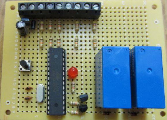
We are currently working on a project which has been updated to require the use of a 5 position rotary selector switch (knob). Each position of this switch corresponds to one mode of operation of the full device, and so we need our microcontroller to know which of the five possible positions the switch is in at any given time.

Unfortunately, due to the amount of inputs and outputs already connected to the microcontroller (PICAXE-18M2) used in this project, there is only one spare pin left – but it is an ADC pin (analog-to-digital converter) so all is not lost.

We decided to use something along the lines of a resistor ladder (Wikipedia link), but simplified to reduce the component count as the circuit board is already pretty full.

5 position rotary selector switch resistor ladder to one ADC pin

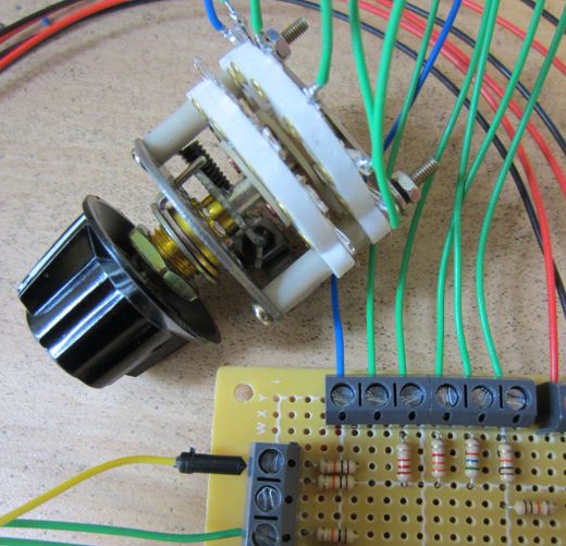
The image above shows the selector switch with +5V going into it up the blue wire, and then the wires corresponding to each position of the switch coming down the five green wires. When in position 3 for example, +5V is present on the third green wire, and the rest of the green wires are connected to nothing.

If we had lots of spare IO on the microcontroller we could just connect each of the five switch outputs directly to five individual microcontroller pins (not forgetting to add pull down resistors).  What we instead had to do is put together the following very simple circuit.

Resistor ladder for one ADC pin and rotary selector switch
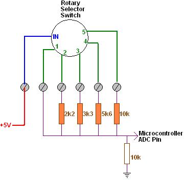
When the switch is in position one, +5V goes straight into the ADC pin on the microcontroller. When the switch is in position two, a voltage divider (Wikipedia) is formed with Vs = +5V, a 2k2 (2,200 Ohm) resistor as R1 and a 10k resistor as R2. Therefore the ADC pin will see Vo which is Vs * (R2/(R1+R2)) = 4.10 Volts. Switch position three sends 5V through a 3k3 10k voltage divider outputting 3.76V, position four through a 5k6 10k voltage divider outputting 3.21V, and position five through a 10k 10k voltage divider outputting 2.50V.

Using the 10-bit ADC pin on the 5.00V powered microcontroller, a numerical value from 0-1023 is assigned proportional to the voltage (0-5V) arriving on the pin. So, position one (analog 5V) is given the digital value 1023, position two (4.10V) is 839, position three (3.76V) is 769, position four (3.21V) is 657, and position five (2.5V) is 512.

These calculated ADC values will not be exact as the resistance of the resistors will change a little with temperature, the 5V regulator feeding the microcontroller may fluctuate a little etc – therefore, we actually use ranges instead of exact values to work out within software which switch position is selected – e.g. position three is 769, but as position two is 839 and position four is 657, we can say that the switch is in position three if the ADC value from the arriving voltage is in the range 714 to 803.

This is all relatively simple to set up in the software – we just added a short PIcaxe subroutine called whichMode which does the readadc10 command on the relevant pin and sets a variable modeValue to the mode value (1,2,3,4 or 5) to which the ADC value corresponds.
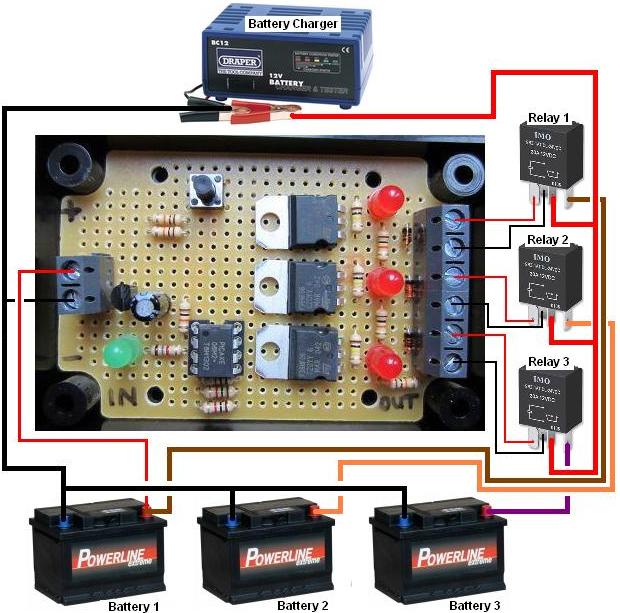
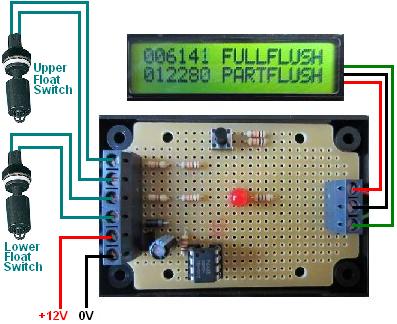
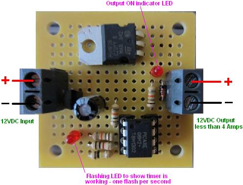
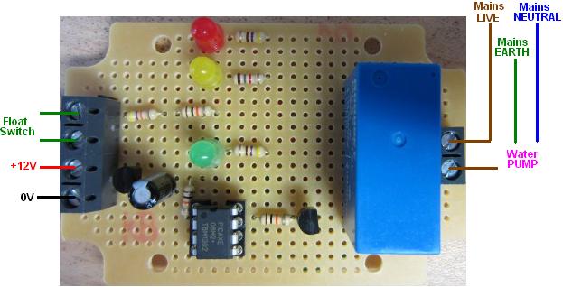
Project of the Day – Drifting Radio Buoy Timer

In addition to our user programmable REUK Super TImer and Super Timer 2 products we make a large number of other timers to order specific to the needs of individual projects.

drifting buoy timer

Today we put together a timer for a very interesting project – a drifting buoy designed to measure various metrics such as salinity, temperature, and location, and transmit them over a radio link at regular intervals as the buoy drifts on tides and currents in the sea. Our timer turns on the power to the buoy electronics for half an hour once every six hours so that it can collect and transmit data. The maximum total current draw to be switched by this timer is 2 Amps at 12VDC.

Although the timer will be fitted in an airtight container, we thought it better not to use a mechanical relay as high humidity and the marine environment is very corrosive and can cause relays to fail rapidly. Instead we made the whole timer solid state with a MOSFET used to switch the output current. We also made it nice and small and used very low power LEDs with high resistor values to minimise power consumption of the timer itself. All component values user were over-specced for greater reliability.

If you need any kind of timer, email neil@reuk.co.uk with full details of your requirements.

Project of the Day – Multiple PIR Sensors to Control Multiple Lights

Today we finished work on the controller pictured below which was produced to control lighting in a Halloween maze using motion sensors.

Halloween PIR motion detecting lighting controller

The maze will be in the dark, but with three passive infrared (PIR) motion sensors located through the maze and used to turn on three lights when motion is detected nearby – the first PIR sensor controls the first light, the second sensor the second light, and so on, independent of each other. When motion is detected by a sensor, the relevant light turns on for just 3 seconds, and then that light will not turn on again for at least another 30 seconds.

PIR motion sensor module

The PIR modules chosen for this project were KC7783R PIR Modules which are very small and easy to hide, and have very low power consumption. As the light bulbs themselves have yet to be chosen, we fitted three 10A rated relays to switch the power supply to each bulb.

Halloween PIR lighting controller circuit connections

The controller board is fitted with three small red LEDs, each one reflecting the output of one PIR sensor. Therefore the status of each sensor can be checked even during the 30 second delays that lights do not turn on after a recent motion detection.

This circuit design is based around an ATmega328 microcontroller as an Arduino standalone.

If you need any electronic controllers taking inputs from a motion sensor or sensors, send an email to neil@reuk.co.uk.

Project of the Day – Fold up Car Mirror Controller

Pictured below is a project we have completed for a retro-fit automatic folding car door mirror controller.

Automatic car door mirror controller

The car in question is a Japanese 4×4 with fold up mirrors and an after market OEM mirror switch fitted to raise and lower the mirrors when buttons are pressed in the vehicle. The goal of our controller is to automatically fold up the mirrors when the car is central locked, and to automatically fold down the mirrors when the car is central unlocked.

As things stood, when the ignition is on, if the fold up button is pressed, +12V is sent from the mirror switch to turn the two mirror motors in one direction, and if the fold down button is pressed, +12V is sent to turn the mirror motors in the other direction. Our controller sits between the mirror motors and the mirror switch and replicates this behaviour detecting the +12V signals and outputting the same to the mirrors for as long as a signal is present. But, when the ignition is off, there was no way to fold or unfold the mirrors.

When the car is central locked (ignition off) a +5V signal is present for one second on the wiring loom, and when it is unlocked another +5V signal is present. Our controller is designed to detect these signals, and if the ignition is off, to output +12V to turn the mirror motors in the required direction for a user programmable number of seconds immediately after detecting that the vehicle has been locked or unlocked. This gets the mirrors to automatically fold down ready for driving when the car is unlocked, and fold up out of harm’s way when the car is locked.

This controller was built around the ATmega328 microcontroller as a standalone Arduino project. Email neil@reuk.co.uk if you have an automotive electronics project of this type.