Low Voltage Disconnect with Early Warning Alarm

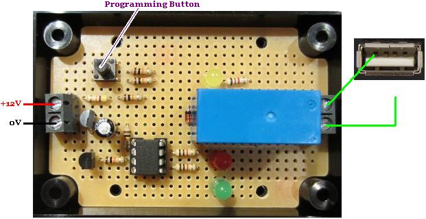
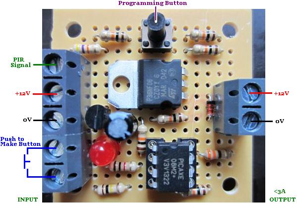
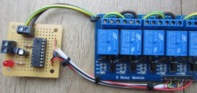
Pictured below is another of our low voltage disconnect (LVD) circuits designed to protect batteries from being overly discharged.

12v low voltage disconnect for latching relays with early warning buzzer and LED
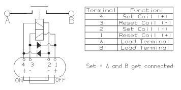
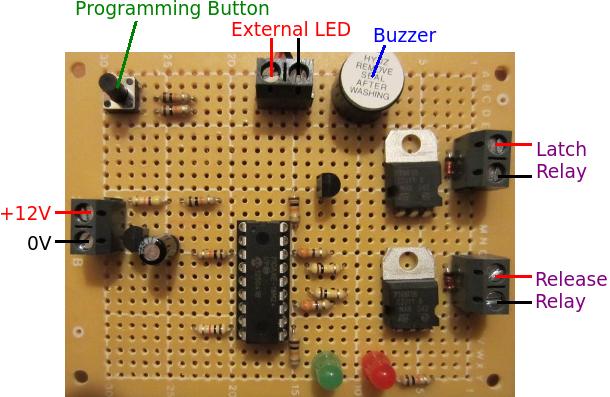
This particular LVD has a few added features. First of all, to reduce power consumption by the LVD itself, it has been designed to work with a latching relay. The chosen relay (click here to download the latching relay datasheet) has two coils – one coil to latch the relay closed (set coil), and the other to release the relay (reset coil).

latching relay connections for low voltage disconnect
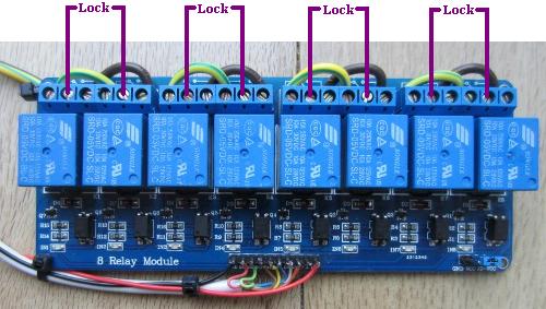
This controller can be programmed as per our standard REUK Programmble Low Voltage Disconnect with the disconnect voltage and cancellation voltage. While the voltage is good, the relay will be left latched closed, and then when the voltage falls below the disconnect voltage, it will be latched open.

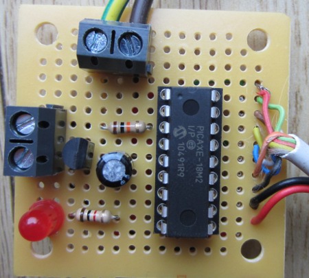
As an added feature, when the measured battery voltage is 0.2V or less more than the disconnect voltage, the external LED (which can be panel mounted somewhere easily visible) turns on, and an on board piezo buzzer sounds briefly every half a minute until either the user starts to charge the battery, or the disconnect engages due to even lower measured voltage.

If you need any kind of low voltage disconnect circuit, email neil@reuk.co.uk with details of your exact requirements.

Dawn Dusk Automatic Hen House Door Controller

Pictured below is a hen house door controller which will automatically open the hen house door in the morning and close it again at night to protect the birds from foxes and other predators.

Automatic hen house door controller with dawn dusk light detector and limit switchesThis controller is somewhat based around our Simple Hen House Door Controller which uses a low voltage programmable digital timer to set when the door should open and close.

This version instead takes an input from a light detector (click here for our article introducing Light Dependent Resistors), and uses this to detect dawn and dusk.

When dusk begins, the motor turns one way to lower the door until it presses against and closes the lower roller switch which acts as a limit switch. Similarly, when dawn begins the following morning, the motor turns the other way to raise the door until it closes the upper roller switch.

(For the explanation of how the polarity of the voltage sent to the motor is reversed see our introductory article: Automatic Hen House Door Controller).

In order for the user to set the light level threshold at which day becomes night and night becomes day, a programming button is provided on the circuit board. When the ambient light level is at the level considered by the user to be the threshold, they press this button while powering on the controller to save that measured light level as the new threshold. The threshold is stored in permanent memory and is therefore not lost even when the controller is subsequently disconnected from the power.

connection diagram for Arduino based dawn dusk hen house door openerPictured above is a functionally identical controller, but which is built around an Arduino Pro Mini instead of the PICAXE-18M2 used in the original. The instructions for this controller are available here: Dawn Dusk Henhouse Door Controller Instructions.

If you need any type of door controller contact neil@reuk.co.uk with details of your exact requirements.

Automatic Low Voltage UPS Shutdown

Pictured below is a special low voltage disconnect controller designed to switch off an uninterruptible power supply (UPS) when the battery bank to which it is connected is low on charge.

Low voltage detecting automatic shut down for Uninterruptible Power SupplyThe system for which this controller was built is as follows. A 72V 2.3 kW solar PV array is connected to a 48V 50A MPPT solar charge controller. The charge controller charges a 48V battery bank (made up of an array of 12V batteries); and that feeds a 3.5 kW UPS  which supplies electricity to the house.

The UPS does not have a low voltage disconnect feature and so from time to time the batteries were being discharged too far. Obviously the owner wanted to avoid this as the battery bank is a very expensive part of the system.

This particular UPS has a standard female USB port on it, and if its pin1 is shorted out with one of its other pins, the UPS switches off.

Therefore our controller is a slightly modified version of our standard programmable low voltage disconnect. One of the 12V batteries in the battery bank is constantly monitored. If the voltage measured stays below a user set low voltage threshold (e.g. 12.0V) for 10 seconds, the on board relay closes for 2 seconds which shorts two of pins in the USB socket and forces the UPS to switch off immediately. Therefore the battery bank is protected from being run down excessively.

Raspberry Pi GPIO with BerryIO

Today we have been trying out BerryIO – a control system for Raspberry Pi which is web browser based for ease of use and set up.

Although BerryIO can be used to monitor the system status of a Raspberry Pi; of most interest to use was the ability to easily control GPIO without any need for programming experience. This makes home automation via mobile phone, tablet, or desktop PC a realistic option even for relatively basic users.

Installation is achieved by entering the following commands at the prompt:

wget -N https://raw.github.com/NeonHorizon/berryio/master/scripts/berryio_install.sh
chmod +x berryio_install.sh
sudo ./berryio_install.sh

followed by:

berryio help

just to make sure it is working.

With BerryIO installed on your Raspberry Pi, you simply enter the IP address of the Raspberry Pi in the web browser on your phone, tablet, or PC, and after entering your Pi username and password when prompted you get a menu of options of which we found GPIO, camera (if you have one), and system status to be the most useful.

Raspberry Pi BerryIO - GPIO ControlSelecting GPIO from the menu, all of the GPIO pins are shown and you can set them individually to be either NOT IN USE, IN (for inputs), or OUT (for outputs).

BerryIO GPIO inputs Raspberry PiIf you select IN for a pin (for example GPIO-7) as shown above, when a high signal arrives on GPIO-7 the green light turns on, and when the signal arriving is low, the green light is turned off. The web browser updates the status of the GPIO pins in real time – therefore no need to refresh the browser for updates.

Raspberry Pi GPIO outputs controlled from web browser BerryIOIf you instead select OUT for a pin, a toggle switch appears below the selector. Click on ON to turn on the output (green light illuminates for that GPIO pin in the browser), or click OFF to turn off the output (green light turned off).

The system status shows a few bits and pieces of information about memory, storage, loads etc, but this does not currently update in realtime so you have to refresh the browser for the latest data.

raspberry pi system status - BerryIO

We will be looking into some useful real world useful applications for BerryIO, but it is certainly well worth installing it and having a play around with it just for fun.

BerryIO is still under development and new features and functionality are still being added to it. The release of an API for mobile app development should hopefully result in some interesting and useful tools being developed to control the Raspberry Pi remotely via a simple user interface.

Full details of BerryIO and the installation instructions are available here: install BerryIO.

12V Programmable PIR Timer with Override

Pictured below is a modified version of our standard 12V Programmable PIR Timer with 3A Output.

pir motion sensor timer controller with override

The standard version turns on an output after motion has been detected, and keeps the output on until a user programmed time has elapsed.

This new version retains all the same functionality as the original, but has the addition of a pair of screw in terminals into which the contacts for an external push to make button can be connected.

The software on the microcontroller has been modified for this version to provide manual override functionality. If the output is off (because no motion has been detected), pressing the override button (for more than half a second) turns on the output and the red LED flickers constantly.

To cancel the manual override, the override button is again pressed for more than half a second which turns off the output.

If the override button is pressed while the output is already on (from a recent motion detection event), then the output will be turn off.

If you need any type of PIR sensor linked timer/controller, email neil@reuk.co.uk with details of your exact requirements.

Arduino SD Card Datalogging

We recently published our Arduino Solar Water Heating Pump Controller Design and Code which shows the basics of putting together a very simple solar water heating pump controller which you can then extend to add the other features you require. (Click here also for our Introduction to Arduino.)

The feature about which we have received the most questions is datalogging functionality to generate a log file of the temperatures recorded and the status of the pump (on or off).

Arduino SD card temperature datalogger

Pictured above is a demonstration on prototyping breadboard of how datalogging can be achieved using an Arduino SD Card Module (click link to buy). These are available from just £0.99 including delivery for standard SD cards (and from around £1.60 including delivery for modules for micro SD cards).

Arduino SD card reader moduleSD card modules for Arduino are very simple to use. SD cards operate on 3.3V, but the Arduino on 5V; however, these modules have all the necessary components fitted to bring down the voltages and enable safe reliable operation without the need for you to add any external components.

In the breadboard demonstration above, we have a single LM335 temperature sensor connected to the A0 pin of an Arduino Nano as per the solar water heating pump controller design (linked to at the start of this post).

We then have the following connections between the Arduino and the SD Card module:
Arduino D10 to SS (slave select)
Arduino D11 to MOSI (master out slave in)
Arduino D12 to MISO (master in slave out)
Arduino D13 to SCK (serial clock)
We also connected the 5V and GND pins of the Arduino to the corresponding SD Card module connections to power it.

Note that some SD Card modules have their connections labelled differently.
CS=SS, DI=MOSI, DO=MISO, and CLK=SCK.

For this demonstration we just want to create a text file (called templog.txt), measure the temperature once per second, and add each temperature reading to the end of the file to form a very basic datalog.

Arduino temperature datalogger sd cardThe stored data on the SD card can then be viewed, manipulated, and graphed on a PC. Multiple temperature sensors (or other sensor inputs) can be added and logged by extending the bare bones Arduino code above.

arduino rtc real time clock module

For a more advanced datalogger, the next key element to add is an RTC (real time clock). Using an RTC each data point can be logged alongside the exact time that it was recorded. Arduino RTC modules including a backup rechargeable button cell are available very cheaply. We will show you how add an RTC to an Arduino datalogger in a future post.

Automatic Horse Feeder Controller

Pictured below is a controller for an automatic horse feeder. This device is made up of a 12V digital programmable timer, a microcontroller board, and an eight relay board.

automatic horse feeder

The horse feeder hardware comprises four shelves onto which the owner can put feed. Four car door locks are used to release the shelves one at a time to release the feed and drop it down to where the horses can access it.

When 12V at one polarity is supplied to a lock, it will perform a pull action; when the polarity is reversed it will perform a push action (which resets the lock ready for the next time it is to be used).

automatic horse feeder control board

The programmable digital timer is set by the end user to turn ON for one minute at the times of day that the horses need to be fed. Our controller (pictured above) receives power when the timer is ON, decides which feeder should be released next, pulls the corresponding lock to release the feed shelf, waits a couple of seconds, and then pushes the lock to reset the feeder.

To enable the polarity supplied to the locks to be reversed, eight SPDT relays are used for which we used a commercial relay board (click here to buy relay boards of this type). We connect 0V to all the relay NC’s, and +12V to all the relay NO’s, then for each pair of relays, we connect the COM’s to the lock power inputs.

automatic horse feeder relay board connectionsIf we close one relay in a pair we get one polarity supplied to the lock (since it sees +12V and 0V), and we we close the other relay, we get the other polarity (since it now sees 0V and +12V).

underside of automatic horse feeder relay boardIf you have a process to automate in a way similar to this example, email neil@reuk.co.uk with details of your exact requirements.