Rainwater Toilet Flush Pump Controllers with LCD

We have been making a bespoke range of controllers for people who would like to use rainwater for their toilet flushes for around 6-7 years now. Here is an example of one of our early Rainwater Toilet Flush System Controllers with details of how such a system works.

rainwater pump controller with LCD display and empty water butt sleep function
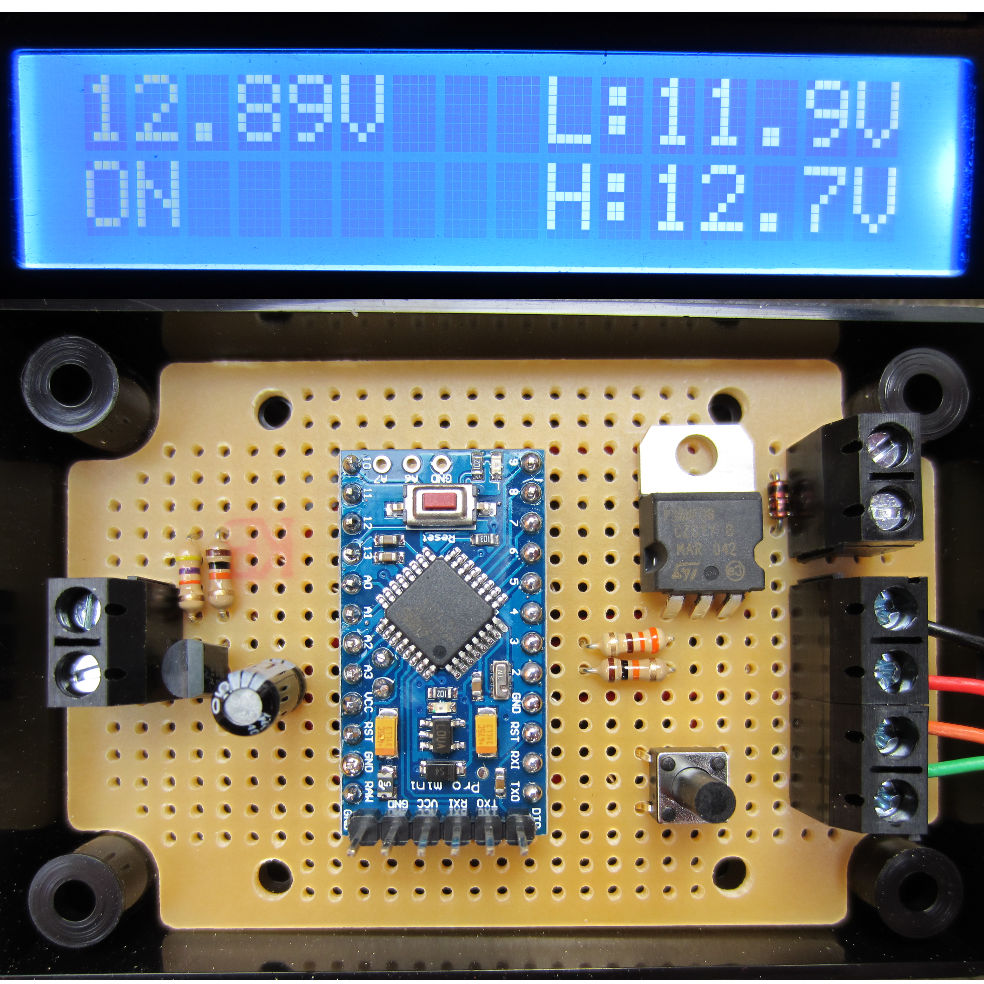
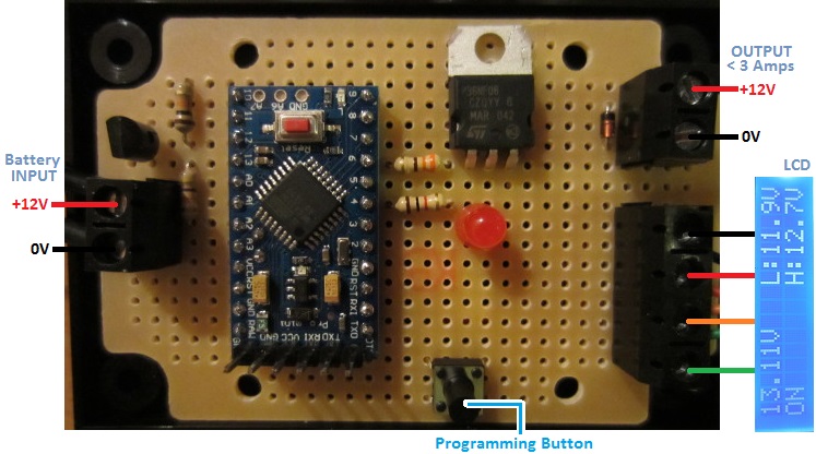
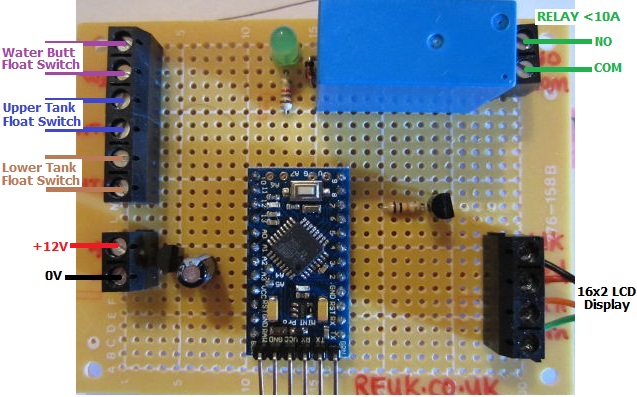
Pictured above is one of our more advanced systems which includes an LCD display to keep the user up to date with the status of the system and water levels in the water butt and header tank (which gravity feeds to the toilet cisterns in the home).

In this particular case, if the two float switches in the header tank are not in water, the tank is empty, and so the pump turns on to fill the tank. If there is sufficient water in the water butt to fill the tank, then the pump will stop when the tank is detected to be full. If however the water butt is empty (or becomes empty during pumping), then then controller sleeps for four hours to allow a rain shower to collect a good amount of rainwater (if it rains in the meantime) so that pumping later will fill the tank.

rainwater controller system normal LCD display
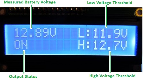
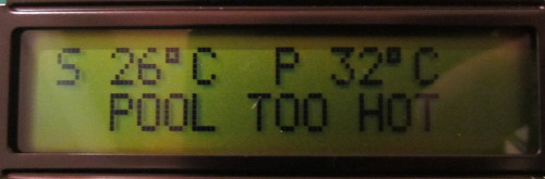
The display constantly shows the status of the water butt (WB) – either OK or LOW (empty), and the status of the header tank (HT) – either EMPTY, OK, or FULL. The bottom line of the display shows whether the pump is running, the controller is sleeping, or everything is just ticking along as it should.

rainwater pump controller with mains water solenoid and LCD display
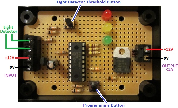
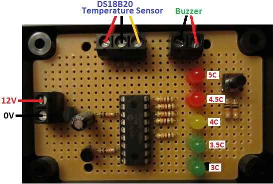
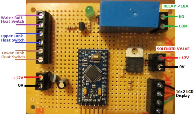
The controller pictured above is a little more advanced. If the header tank is detected to be empty, then the pump will start as normal unless the water butt is also empty. If during pumping, the water butt becomes empty (or if it is already empty when the header tank is detected to be empty), a solenoid valve will close which will allow the flow of water up the rising main to enter the header tank to ensure that the toilets can always be flushed without any manual intervention.

rainwater controller with solenoid valve activated
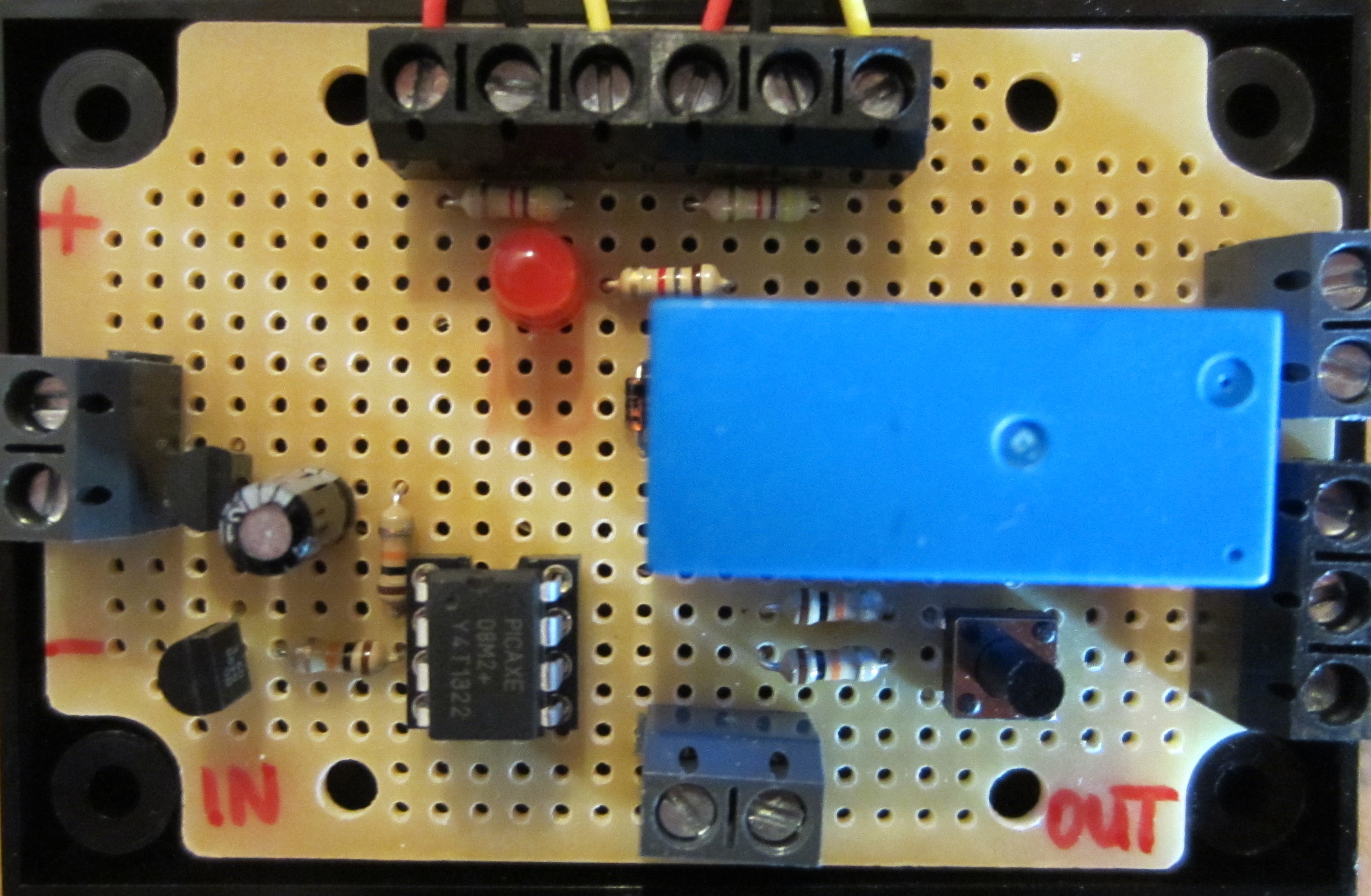
The display for this particular controller also shows the user when the solenoid valve is open so they know that you are using mains water due to a lack of stored rainwater in the water butt. There is no need for a four hour delay with this unit since every time the header tank empties and the water butt is either empty or becomes empty during pumping, the mains water supply will top up the header tank.

This controller is based around an Arduino Pro Mini microcontroller development board and uses standard horizontal float switches in the water butt and header tank to detect water levels.

If you need a rainwater toilet pump controller of any type, please email neil@reuk.co.uk with details of your specific requirements.

New Raspberry Pi Model B+

We have just received our new Raspberry Pi Model B+. This is not the Raspberry Pi 2 or C (which is likely to be released in 2017), but is instead a Model B with a few very useful changes and additions.

Raspberry Pi Model B+

The biggest addition is a further two USB ports bringing the total up to four USB 2.0 ports. This is particularly useful since a mouse and keyboard would use all the ports on the Model B leaving no ports free for thumb drives, and other peripherals without the use of a secondary powered USB hub.

Raspberry Pi B+ can now be configured to output a total of 1.2 Amps in total (0.6A by default) from its USB ports (assuming a good quality 2A power supply is used). Therefore external hard drives can be used without the need for a powered hub.

The original SD card slot has been replaced by a micro-SD card which means no more SD card sticking out of the Raspberry Pi, and it is easier and cheaper to buy micro-SD cards.

A further 14 GPIO pins have been added to the 26 pins found on the Raspberry Pi Model B for a total of 40 GPIO pins for hardware projects. The layout of the first 26 pins has been kept the same for backwards compatibility.

Finally, power consumption has been reduced a little, sound quality has been improved with the audio connector changed to integrate composite video, and the overall layout of the board has been changed and mounting holes added to the corners of the board.

The processor and RAM (512MB) remain unchanged.

We will be doing some interesting projects with our new Raspberry Pi B+ over the next few weeks and months to make use of the additional functionality offered by this new model.

Pyboard Python for Microcontrollers

Pyboard python for microcontrollersPictured above is the Pyboard – an open source prototyping platform designed and manufactured in the UK. This board with its ARM microcontroller (STM32F405 clocked at 168MHz) is programmed using micropython a low memory usage version of the Python 3 scripting language.

The board has LEDs, microswitches, a built in accelerometer, and 30 general purpose IO connections (including 4 PWM, 14 ADC, I2C, and SPI pins) for connection to external components and analogue/digital sensors for your projects.

The board has 1MB of on board flash memory, 192KB of RAM, and also a micro SD card slot which can be used to store scripts and hold project generated data. It has a built in USB interface.

Pyboard fits in the marketplace somewhere between Raspberry Pi and Arduino. A Raspberry Pi is a full computer which means that it can be complicated to use, power hungry, and large in size. An Arduino is simple to use, has lots of useful GPIO and shields, and they are available in small versions, but they are not very fast and scripts need to be compiled on a PC before loading them to the Arduino. Pyboard is perfect for processor intensive stand alone projects – particularly for anyone who already has experience programming with Python.

Pyboard is just 33 x 40mm in size and weighs just 6g.

The official Micro Python website is here, and the tutorial which shows how to get strarted with Pyboard and Micro Python is here: Micro Python Tutorial.

New REUK Low Voltage Disconnect with Display

Pictured below is the new REUK Programmable 12V Low Voltage Disconnect with LCD Display. This device allows batteries and battery banks to be protected from being too deeply discharged, and also enables battery  monitoring.

reuk low voltage disconnect with displayFor full details, instructions for use, and to purchase, click here: REUK 12V LVD with LCD). It has been added to the existing low voltage disconnect circuits in the REUK Shop.

Valiant PremiAIR 4 Stove Fan

In our article Valiant Heat Powered Stove Fan published back in 2012 we reviewed the FIR300 Self-Powered Stove Fan from Valiant and showed how this device can help increase the temperature in the room being heated by a logburner or multifuel stove.

Comparison of Fir300 and Fir361 stove fans from ValiantThe reviewed FIR300 stove fan is pictured above on the left next to the new PremiAIR 4″ Stove Fan (FIR361) also from Valiant which we will soon be reviewing in detail.

The immediately obvious differences are the four blades instead of two which should increase the air flow, a new motor, and a more compact design with the motor housed within the heatsink rather than protruding out from it.

The heatsink on the new PremiAIR 4″ has a larger surface area with a new design for faster heat dissipation. Therefore more power should be available to the motor by the seebeck effect increasing the effectiveness of the stove fan.

Rear view of Fir361 PremiAIR 4 inch stove fan from ValiantWhen reviewing the FIR300 stove fan, we used an accurate digital thermometer and manually logged the temperature in the room minute by minute. For our FIR361 review we will put together a multi-sensor datalogger using a Raspberry Pi and/or Arduino to collect much more data for analysis so that the effectiveness of the fan can be judged – one sensor at sofa height, one at ceiling height, one close to the stove, etc.

UPDATE JAN 2014 – We have now published our detailed article: Valiant PremiAIR 4 Heat Powered Stove Fan Testing on the REUK website. In the end, rather than building another SD Card Datalogger for this project, we used a Raspberry Pi Model A+. We will be publishing a detailed article in the coming months on how we programmed and set up this datalogger (including the source code), and also how viewed the data in real time through a mobile phone browser.

REUK Super Timer with Light Detector Override

Pictured below is a new device which mixes the features of the REUK Super Timer 3 and the REUK Dawn/Dusk Lighting Controller.

REUK Super Timer with light detector overrideThe timer can be programmed with different ON and OFF time durations from 1 second to 99 hours with various modes of operation available. When the time is ON, there is a 12V output (rated at up to 1A) which can be used to control up to 10-12 Watts of 12V devices, or used to switch a relay if higher currents or different voltages are to be switched.

The modification is the addition of a light detector (light dependent resistor) which is used to override the timer at night time. When the ambient light level is measured to be less than the user set threshold, then when the timer is ‘ON’ the output remains off.

This particular board is for an automatic fish feeder which directly drives a small motor, and the override is to prevent the feeder operating at night.

If you need a timer similar to this, email neil@reuk.co.uk with details of your exact requirements.

Low Voltage Disconnect with LCD Display

Pictured below is our latest low voltage disconnect circuit with LCD display.

REUK low voltage disconnect with LCD displayAs with our standard programmable low voltage disconnect (LVD), this device is designed to protect batteries from being discharged too deeply and permanently damaged. The user can set the low voltage at which the output loads will automatically be switched off, and also the higher cancellation voltage above which the output loads will be switched back on again.

LCD display on REUK low voltage disconnect (LVD)This particular LVD has a backlit LCD on which system information is constantly displayed. It is also used when setting the low and high voltage thresholds which makes things  a lot clearer and simpler than using LEDs or a rotary switch to programme those in.

As shown above the display shows the measured battery voltage updated multiple times per second and given to 2 decimal places of resolution (and calibrated to be accurate to within +/- 0.02 Volts across the range 10-16V).

The system status is usually ON or OFF, but can also be LOW or HIGH when the battery voltage is transitioning one of the thresholds about to change the state of the system. The high and low threshold voltages are also permanently displayed.

In order to avoid the output cycling on and off too often (particuarly as the battery voltages can spike or dip depending on the loads they are powering) there is a time delay during which the voltage must remain under/over the voltage threshold before the system will change from ON to OFF or OFF to ON respectively. During that time delay the backlight of the display flashes as a visual indicator that the threshold has been breached. We chose to flash the display itself rather than flashing an LED either on the board or on leads, since it is much easier to panel mount just the LCD than to mount both that and an LED indicator.

This particular client-tailored LVD has a MOSFET directly switching the output loads which can have a maximum total rating of 3 Amps. We can also make this with a relay fitted on board for direct switching, or a lower rated output which can be used to energise a high current (or high voltage) rated relay external to the board – e.g. an automotive relay or a solid state relay (SSR).

This low voltage voltage disconnect with LCD is now available direct from the REUK Shop. Click here to find out more or to purchase now: buy REUK Low Voltage Disconnect with LCD.

We will shortly be adding a very similar unit with the addition of datalogging functionality. Over the last couple of years we have sold many LVDs with built in dataloggers (see here for an example: Low Voltage Disconnect with Display and Datalogger), and we now have refined things to the point that the product is ready for general sale. In the meantime, if you have any requirement for a low voltage disconnect with or without a display and with or without datalogging, please email neil@reuk.co.uk with details of your requirements.

Frost Warning Thermostat with Temperature Indication

waterproof thermostat frost warning devicePictured above is a project we have recently completed for a special thermometer thermostat for an automotive application. The requirement was for a device which would show the temperature using LEDs, and would sound a warning buzzer for a couple of seconds when the measured temperature falls to or below a user set temperature threshold (in this case chosen from within the range 3- 5 degrees Celcius).

ds18b20 stainless steel temperature probe - waterproof

A waterproof temperature sensor was required for this project, and good accuracy and reliability was also essential. Therefore we chose to use a stainless steel encased DS18B20 digital temperature probe – the same sensors we use in our swimming pool solar water heating pump controllers amongst other things.

The button on the circuit board can be pressed by the user to change the temperature at or below which the attached buzzer will sound. When the temperature is above 5 degrees, both red LEDs are on. When the temperature is below 3 degrees, both green LEDs are on. When the temperature is in the range 2.76 to 5.24 degrees the LED which corresponds to the nearest temperature to that measured it on.

If you need a thermometer or thermostat along similar lines to this unit, email neil@reuk.co.uk with details of your exact requirements. We can also add 16×2 LCDs (displays) upon request.


Solar Water Heating Swimming Pool Controller with Display

Pictured below is another of our solar water heating pump controllers – this time with digital waterproof temperature sensors (DS18B20), and an LCD to show the measured temperatures of the solar heating panel and swimming pool as well as system status and for the user to programme in the settings.

Solar water heating pump controller with LCD and maximum temperature overrideAs this controller is to be used in sunny Australia it includes a pre-programmed maximum temperature override to prevent the swimming pool from getting too hot. When the pool is measured to 31 degrees Celcius or hotter, the pump will not to be turned on again until the pool temperature has fallen to 28 degrees.

LCD display for solar water heating pump controller

Pictured above is the LCD showing the solar panel temperature of 26 degrees C, and the pool at 32 degrees C. Therefore the pool is too hot and even when the solar panel temperature increases, the pump will not turn on.

At the bottom of the circuit board is a pair of screw in terminals which will be connected to the output from a 12V programmable digital timer. In the winter, the customer for this controller wants to be able to automatically run the pump at the same time each day for a certain time just to circulate water around the system.

If you need a solar water heating controller for any application, with or without a display, email neil@reuk.co.uk with details of your exact requirements.


Raspberry Pi GPIO Sensor Readings to Twitter

We have just published a new article Publish Temperature Sensor Readings to Twitter with Raspberry Pi to the REUK.co.uk website which includes full details on how to get sensor measurements from a Raspberry Pi up to the internet for remote viewing.

Raspberry Pi and TwitterWe will soon be returning to this to look at how batteries can be monitored, solar generation can be monitored, and many other similar projects.

We will then be showing how devices can be controlled from Twitter – for example, you could turn on your immersion heater element with a Twitter message if your Twitter feed tells you that your water tank is cold and you are on the way home and would like a hot bath.