Multi Level Low Voltage Disconnect with Display

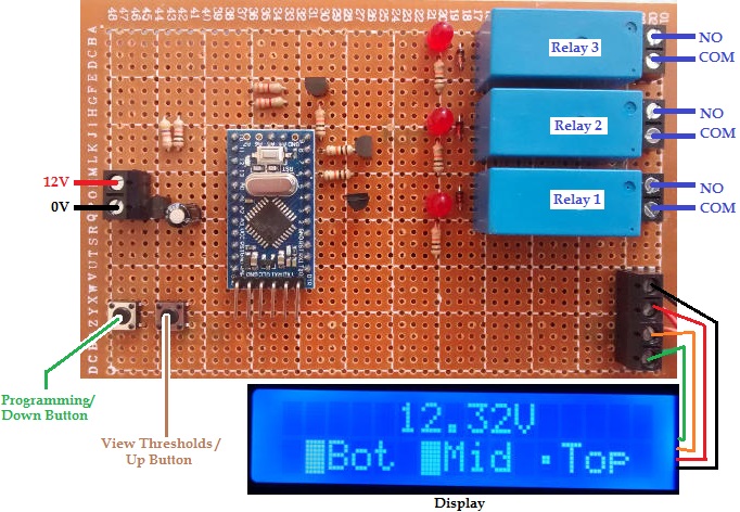
Pictured below is a special multi level low voltage disconnect controller which we recently made. As with our other low voltage disconnect products, this device is designed to automatically disconnect loads from a battery when the battery voltage drops below a user set threshold. The loads are then reconnected when the battery voltage has risen above a second higher threshold.

Three level low voltage disconnect (LVD) controller with relays and display

What makes this low voltage disconnect special is that it can be programmed with three independent pairs of voltage thresholds, and control three sets of loads. If you have a selection of devices powered from your 12V battery, some will be more important than others, and some will use more power than others. Having multiple LVD voltage thresholds allows you to choose which devices should have their power cut first as the battery charge level goes down. Cutting the power to high consumption low importance devices leaves more charge available to keep the more critical devices going for as long as possible.

If the battery was powering a large amount of lights for example, one light could be connected to the lowest voltage threshold output to stay on as an emergency light, while the rest of the lights could be turned off at a higher threshold. On a boat, the fridge and navigation system would be connected to the lowest threshold output, while the television and most lighting could be connected to a higher threshold.
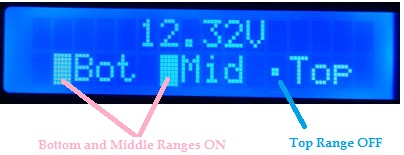
display for three level low voltage disconnectThe standard display shows the voltage measured on the battery, as well as the status of the three outputs corresponding to the Bot (Bottom), Mid (Middle), and Top ranges. In the image above, at a battery voltage of 12.32V, the Top range is off while the other two remain on.

all outputs off low voltage disconnect

At a lower voltage (10.55V shown above), all three outputs are off.

all outputs on low voltage disconnect

…and then with the battery voltage fully restored (13.53V while being charged), all three outputs are on.

By pressing the View Thresholds button, the user set voltage ranges are shown on the display.
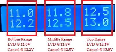
Showing the voltage ranges for the multi threshold low voltage diisconnectAbove for example the bottom range has the low voltage disconnect at 11.0V and the cancellation voltage (at which the output will be turned on again) at 12.2V.

programming the multi threshold low voltage disconnectProgramming the six voltage thresholds is done using the two on board buttons. These thresholds are stored in non-volatile (long term) memory and are therefore not lost when/if it is disconnected from the battery.

When the battery voltage is measured to have moved above or below a threshold which will result in an output status changing, the back light of the display flashes on and off. The voltage has to remain constantly on the new side of the threshold for 10 seconds before the output status will actually change so that any spikes and dips in measured voltage do not result in devices being turned on or off unnecessarily.

Six Level Low Voltage Disconnect

Pictured below is a similar device we made in July 2018 with six user programmable low voltage disconnects and six outputs to be connected to external relays. six level six output low voltage disconnect lvd
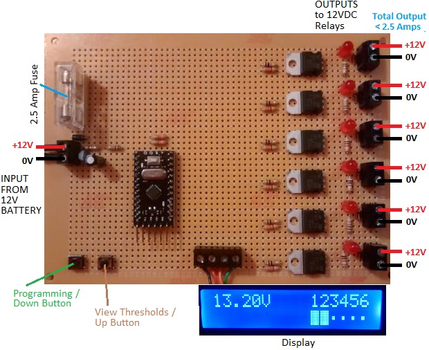
This particular device was made to be used with a 12v immersion comprising 6 individual 100 watt elements which had been controlled by 6 individual programmable relays to dump off excess battery charge and gain hot water.

programmable relays used to control elements of an immersion to use surplus battery charge

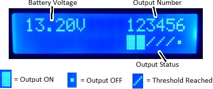
The display for this version shows the status of each of the outputs.

display for multi level low voltage disconnect

And the different thresholds programmed can still be viewed two at a time on the display.

viewing-the-low-voltage-disconnect-thresholds

Programming this device is done in the same way as the original three output version using the up and down buttons on the device to change and set each of the 12 thresholds.

Programming thresholds for low voltage disconnect

Nine Level Low Voltage Disconnect

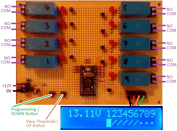
A further development of this is the below pictured 9 level low voltage disconnect from August 2018 with nine independently programmable on board relays to switch various loads.

9 level low voltage disconnect with display

Twelve Level Low Voltage Disconnect

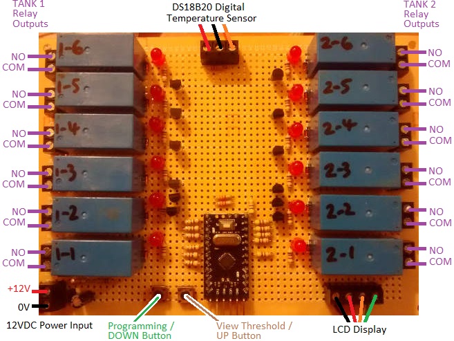
Pictured below is a unique device with twelve independently programmable low and high voltage thresholds.

12 level low voltage disconnect lvd with thermostat control

This device has its twelve outputs (relays) split into two banks of six for use with two hot water tanks and twelve heating elements. When the temperature of the first tank reaches a user programmed high value, the second bank of elements is used to heat up the second tank of water. As with the nine level LVD shown earlier, this device has a display and it shows the battery voltage, tank 1 temperature, and the status of tank 1 or tank 2’s heating elements (depending on which tank is to be heated).

If you need any kind of low voltage disconnect, battery monitor, and/or datalogging device, email neil@reuk.co.uk with details of your requirements.
Intel Curie tinyTILE – Mini Arduino 101

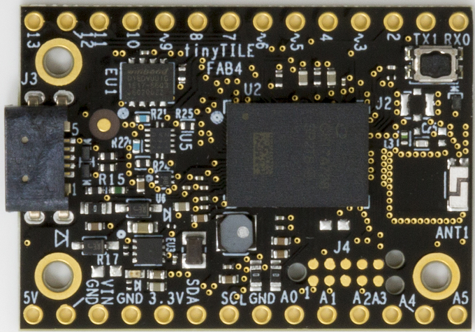
intel curie tinyTILEPictured above is the new tinyTILE development and production platform featuring the Intel Curie module. This board is a miniature version of the Arduino 101 and measures in at just 35 x 26mm (1.38 x 1.02 inches), and has been designed to fit on prototyping breadboards.

The tinyTILE board can be programmed using either the Arduino IDE or Intel’s own software – the Intel Curie Open Developer Kit (ODK), and the I/O connections are functionally identical to those on the Arduino 101.

With its small size, low-power consumption, array of motion sensors (6-axis sensor with accelerometer and gyroscope), and Bluetooth Low Energy (BLE), tinyTILE should be ideal for battery powered wearable devices and any other IoT projects involving motion monitoring.

tinyTILE has a 32-bit 32 MHz Intel Quark SoC, 384 kB flash memory, and 80 kB SRAM. It also includes a digital signal processor (DSP) offering quick pattern matching identification of actions and motions.

tinyTile can be USB powered via its micro-USB connector. The board has its own internal 3.3V regulator and 3.3V (but 5V tolerant)  I/0 connections.

tinyTILE is available now from element14.com (US+) and cpc.farnell.com (UK) amongst others.

Hen House Door Controller with Voltage Indication

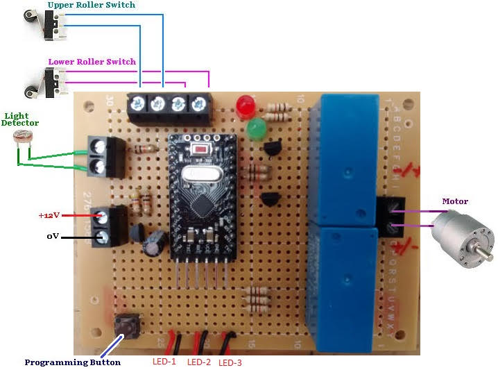
Pictured below is another of our hen house door controllers – this time using a light detector to automatically detect dawn and dusk (user light level calibration), but with the addition of three battery voltage indicator LEDs.

Hen house door controller with low voltage indicationThis device will open and close a hen house door at dawn and dusk respectively when the measured ambient light level dictates. As this device is to be used with a small 12V battery, there is a chance that the battery will go low on charge preventing reliable operation.

Therefore we have added three LEDs (LED-1, LED-2 and LED-3) connected to flying leads so that they can be located somewhere easily visible while the controller itself is in an enclosure to keep it clean and dry.

When the battery voltage is measured to be greater than 12V, all three LEDs are turned on. When the voltage is between 11.8V and 12V, two are on. When the voltage is between 11.5 and 11.8V, 1 LED is on, and when the voltage is below 11.5V, no LEDs are on.

Each day when the user goes into the hen house to collect eggs, they have a quick visual indication of the state of the battery voltage so that they know when they need to think about recharging it.

If you need a hen house door controller, please email neil@reuk.co.uk with details of any specific requirements you may have.

Introduction to TM1638 Display Module for Arduino

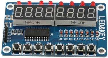
Pictured below is an electronic display module we have been testing out recently.

TM1638 Arduino Display Module

Available at under £2 including delivery (see here: buy TM1638 module), the pictured device offers 8 LEDs, 8 input buttons, and 8 7-segment LED display digits which can be fully controlled with just 3 pins from your Arduino (or other microcontroller unit).

We are looking at these to offer alternatives to the LCDs (liquid crystal displays) we currently use in our solar water heating pump controllers and low voltage disconnects in particular, since the two sets of 4 digits on these modules’ displays can show a voltage to two decimal places plus other information, or two temperature sensors readings also to two decimal places simultaneously. Seven segment displays are much more readable from a distance, and the availability of 8 LEDs and 8 user input buttons opens up many new possibilities.

Initial results of testing have been very positive. If you are interested in getting started with these modules and Arduino, an excellent starting off point is this excellent article: Arduino and TM1638 LED Display Modules from the Australian site tronixstuff.com. All you need is an Arduino board, the Arduino IDE (the software required to programme your Arduino), and the TM1638 library available here.

Programmable Target Shooting Timer Relay Board

Target shooting relay timer controller with display

Pictured above is a target shooting timer relay controller with programmable options for different shooting programmes. With this device the user can set the number of seconds that the target is to remain edge-on to the shooter and how many second that it is to remain face-on to the shooter, and also how many cycles of edge and face the shoot will comprise.

Target shooting timer display

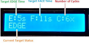
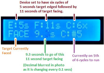
The backlit display with this device shows the user programmed number of seconds that the target will edge (E) then face (F), and the number of cycles (C) for which it will be repeated. It also shows the current status of the target.

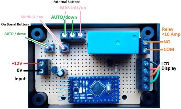
There are two buttons on the controller. The MANUAL button is used to enter the programming mode to set the timings for the programme and also to toggle the target manually between facing and edging. The AUTO button is used to start the programme. The programme starts by edging the target, and finishes also with the target edged.

target shooting timer relay display in action

While the shooting programme is running, the display continues to show the user set programme values and the status of the target. It also shows a running countdown of the time remaining during this part of the cycle, and also which cycle the shooter is currently on.

If you need any kind of automated user-programmable timer for target shooting, please email neil@reuk.co.uk with details of your requirements.

Shooting Timer Instructions

Connect up the timer as shown in the connection diagram at the top of page making sure to use correct polarity for the 12VDC power input. The controller has buttons on board, but external push to make buttons can be connected in parallel to those as shown in the connection diagram.

Programming

To set the timings for your controller, press and hold the UP button for a couple of seconds until the display shows PROGRAMMING MODE. When you release the button, you will be prompted to ‘SET Edge time’. You can use the UP and DOWN buttons to change the displayed value within the range 1-99 seconds. Five seconds after you last pressed a button, whatever is displayed for Edge is saved in memory, and you will be prompted to ‘SET Face time’. Again the UP and DOWN buttons are used to change the displayed value within the range 1-999 seconds. (Since the face time can be set to a high value, if you press and hold the UP or DOWN button, you will be able to speedily increase or decrease the value.) Finally you will be prompted to ‘SET Cycles’. This can be set within the range 1-9 repeating cycles of the Edge/Face times.

The values you set in programming mode are saved in long term memory and are therefore retained if/when you disconnect and subsequently reconnect the power to the controller. You only need to repeat the above described steps if you want to change one or more of the saved values.

Using the Timer

In normal operation with your timings already programmed, the Manual/UP button can be used to manually toggle the position of the target. If the target is face on, press the button, and it will edge. Press the button again, and the target will be face on again.

The relay on the controller is closed when the target is edge on, and open when the target is face on. Therefore, when no power is being supplied to the target, it is expected that your target will be configured to be face on.

To run the timer, press the Auto/DOWN button. All cycles start with the target edge on, so if you have manually set the target to be face on, it will turn to edge on. As shown above, the display will show where you are in the programme, the countdown timer, the target status (edge or face), and which cycle you are currently on.

If you want to stop the timer when it is running, press the Auto/DOWN button again. The target will turn to be edge on if it is not already.

24V Low Voltage Disconnect with SD Card Datalogger

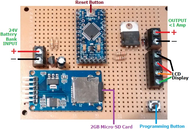
Pictured below is a low voltage disconnect device we recently made for use with a 24V battery system. In addition to the user-programmable low voltage disconnect functionality and LCD display of our standard Programmable 12V LVD with Display, this modified 24V device also includes a full datalogger, storing measured battery voltages at regular intervals to a micro-SD card for later analysis.

24V Low Voltage Disconnect with SD Card DataloggerThis particular unit is destined to be used by a company specialising in the maintenance of the UK’s transport infrastructure; with the low voltage disconnect used to protect batteries from being overly depleted, and the datalogger used to track the rise and fall of battery voltage over time.

If you need any kind of low voltage disconnect and/or datalogging solution, please email neil@reuk.co.uk with details of your requirements.

Solderless Power Supply Module for Breadboard

We recently came across this handy little power supply module designed and built for use with prototyping breadboard (MB102 size) by YwRobot in China.

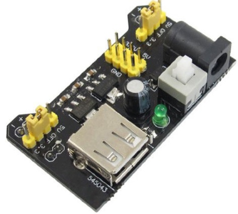
breadboard power supply moduleThis is a very useful device for anyone getting started with electronics thanks to its low cost (approximately £1 delivered) and ease of set up and use.

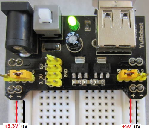
The module simply plugs into a breadboard and gives two pairs of rails which can be configured to give you 2x5V rails, one each of 5V and 3.3V, and you can also set one or both pairs of rails to 0V.

mb102 breadboard power supply modulePictured above we have used the small yellow jumpers to set one pair of rails to 3.3V/0V, and the second pair of rails to 5V/0V. The board is then ready to supply a few hundred mA at 3.3V and 5V to any project you may want to prototype/build on the breadboard.

The module is powered via USB. Virtually everone now has a micro-USB charger at home for mobile phone and table charging etc, so it is surprising that they chose to use a full size USB-A connector. It would have been much better to go for a micro-USB connector.

The module has two low drop linear voltage regulators to supply the 3.3V and 5V outputs. When we tested this with a USB power supply outputting 5.46V, we measured 5.123V on the 5V rail, and 3.286V on the 3.3V rail.

If your USB power supply provides less than 5V (or more likely, you have less than 5V after losses in a long/cheap cable) the 5V rail will always be a few tenths of a Volt lower than the incoming voltage – therefore you cannot guarantee a reliable 5.0V output from this module when powered via USB. Similarly, it is best not to use this connected to a USB port on a PC as the voltage of PC USB ports can jump around a lot depending on what the PC is doing at any particular instant.

There is however a standard DC barrel jack for DC input power. Using a standard 6V DC power supply should give you a full stable 5V output from the module.

There is an on/off switch on the module, with a green LED to show the current status. This is useful not just because it saves you from having to unplug or switch off your USB power supply at the power point, but also because the capacitors in a power supply retain charge after you unplug the power supply and this charge will feed through the module into your electronics project until those capacitors have discharged. That could have unforeseen consequences as the voltage input to your circuit drops.

The quality of the components used and the build quality are as you would expect from a product offered at such a low price, but these modules are still an excellent first purchase for anyone interested in circuit prototyping.

These modules are available on their own, or together with a suitable breadboard and jumper links as a complete starter package. Click here for more information or to make a puchase of one of these power supply modules.

Dawn Dusk Hen House Door Controller with Timer Override

Pictured below is a hen house door controller we recently made for a customer which is a modified version of our standard Dawn Dusk Hen House Door Controller.

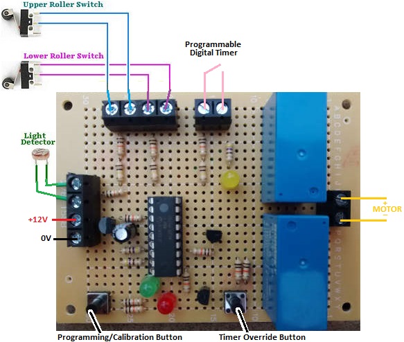
hen house door controller with light detector and timer overrideThis controller will automatically open a hen house door at dawn and close it again at dusk. Dawn and dusk are detected via a light detector, and the user can calibrate the light level at which they consider it to be the transition between day and dusk and between night and dawn to meet their needs.

The modified version pictured above has the additional benefit of a programmable digital timer. We make hen house door controllers with light detectors which automatically detect dawn and dusk, and we also make them with programmable digital timers so that the user can instead set the exact time that the door is to open and close. This particular controller is our first which has both a light detector AND a programmable digital timer for maximum flexibility.

The purchaser of this controller expressed a wish to be able to have the hen house door close at dusk automatically, but also to be able (sometimes) to open the door later (or even earlier) than dawn. Therefore, in the summer when dawn could be at 4am, the timer can be used to keep the door closed until 6am or later to keep the noise down and avoid disturbing neighbours. The programmable digital timer we used can be set with different timings for weekdays and weekends, so for example, the door can be kept closed until much later in the morning on the weekend to keep the noise down.

If you need any kind of poultry door controller, email neil@reuk.co.uk with details of your exact requirements.

New Raspberry Pi 2 Model B – Six Times More Power

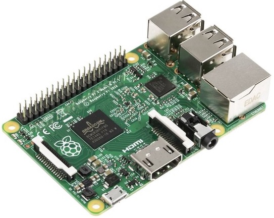
The new Raspberry Pi 2 Model B has just been released, and promises to be six times more powerful than the previous Raspberry Pi models.

Raspberry Pi 2 Model BThe original Raspberry Pi was released around 3 years ago, and since then technology has moved on and competitors have joined the marketplace. The single core 700MHz processor and 512MB of RAM of the recently released Raspberry Pi A+ and B+ make them feel quite sluggish and out-dated, and there are many applications which cannot be used as they run so slowly.

The new Raspberry Pi 2 Model B though has a quad-core 900MHz processor (ARM Cortex-A7) with a full 1GB or RAM,  effectively turned the Raspberry Pi into a low spec PC capable of running the new Windows 10 (which will be offered free of charge for Raspberry Pi to makers!) and the full range of ARM Linux distributions.

The new model is fully backwards compatible with previous models, it will just run everything much faster. You just need the new ARMv7 kernel version of Raspian, and all existing projects will work.

Amazingly, despite the huge lift in specs, the new Raspberry Pi 2 Model B will still be sold for just $35 (around £25-30 in the UK).

Get yours now (in the UK) at cpc.farnell.com.

Programmable Low Voltage Automatic Battery Charger

Our Mini Programmable 12V Low Voltage Disconnect (LVD) is designed to disconnect loads from batteries when the battery voltage falls below  a user set value, and then reconnect the loads when the battery voltage gets back above a second (higher) user set value.

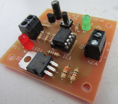
low voltage connect from REUK low voltage disconnectWith a few modifications to the code on the microcontroller of this device it can also be reconfigured as a low voltage connect – a device which will (typically) be used to connect a charger to the battery when its voltage gets low, and then disconnect it when the battery voltage gets higher after charging.

Today we made such a low voltage connect for a customer with a semi off grid garden office, a PV solar charged battery bank, and a selection of lights, 5V chargers, and other low voltage DC loads to be powered. He has a mains powered 5A bench power supply which he wanted to automatically connect to the battery bank via a solid state relay (SSR) when the battery bank voltage fell due to a period of poor solar generation (English weather) or from using a lot of battery power.

With our low voltage connect controlling the SSR, the battery bank will never be able to get overly-depleted and battery power will always be available to power the garden office.

If you need any kind of low voltage disconnect, low voltage connect, or high voltage disconnect etc, please email neil@reuk.co.uk with details of your requirements.