Poultry House Door Controller with Digital Timer

One of our most popular products is this Dawn Dusk Automatic Hen House Door Controller. This device automatically detects dawn and dusk using a light detector calibrated by the user and runs a motor one way in the morning to open a hen house door, and the other way in the evening to close the door. Roller limit switches act to ensure that the door fully opens and closes without over or under running.

Pictured below is a alternative but similar device which uses a programmable digital timer to set the times of day that the door is to open and close.

Automatic hen house door controller with programmable digital timer and roller limit switchesWhen the timer turns on, the motor runs to open the door until the upper roller switch closes. Then when the timer turns off, the motor runs to close the door until the lower roller switch closes.

The advantage of using a timer is that the door can be set to open later on weekends for example to reduce noise from the birds, and the exact times the door is to be opened and closed can be set independently of the level of daylight (and therefore of the weather). The disadvantage is that the timings have to be changed every few weeks as the seasons change and the days get longer and shorter.

If you need any type of automatic poultry house door controller, please email neil@reuk.co.uk with details of your exact requirements.

Rainwater Toilet Flush Pump Controller with Overrun Protection

We make a wide selection of rainwater toilet flush pump controllers for domestic use, and pictured below is another of these.

Rainwater toilet flush pump controllerThis particular controller is designed to be used where there is a very large amount of rainwater storage and a relatively small header tank. In this scenario, if the float switch which detects whether the header tank is full were ever to fail or get jammed with debris etc, 1000’s of litres of stored rainwater could be pumped out through the header tank overflow and lost.

In this controller, the user can programme in a maximum pump running time. If the pump ever runs for longer than that time, it will automatically be turned off, and will not turn on again until there has been manual intervention from the user (checking over everything and resetting the controller).

In standard operation, the controller simply checks the status of the header tank float switch located just below the tank overflow outlet, and shows this status with an LED indicator. Once every four hours, the controller tops up the header tank by turning on the pump and running it until the header tank is detected to to be full.

If you need any kind of pump controller, please contact neil@reuk.co.uk with details of your exact requirements.

New Raspberry Pi Model A+

Pictured below is the latest Raspberry Pi – the Raspberry Pi Model A+ which replaces the old Model A.

Raspberry Pi A+ ModelAs with the Raspberry Pi Model B+ released back in July 2014 (see here: New Raspberry Pi Model B+), the Model A+ has the 40 GPIO pins, reduced power consumption, modified composite video, and a micro SD slot, but the Model A+ still only have 256MB of RAM compared to 512MB for the B+.

The Raspberry Pi Model A+ is smaller than all previous credit card sized Raspberry Pi’s being a whole 2cm shorter in length.

With just the one USB port and no ethernet port, if the Model A+ is to be accessible over your network, you will need a USB WiFi adapter as pictured below installed in the A+.

Raspberry Pi A+ Model with USB WiFi Module

It is likely that the Model A+ will primarily be used as a headless device, but initial set up of Wi-Fi still requires a keyboard and display to be connected – a USB hub is useful at this time. With everything configured, the Model A+ is ready for embedding in your projects.

The following is a very useful guide from How-To Geek which shows how to set up Wi-Fi from the command line: How to Setup Wi-FI on Your Raspberry Pi from the Command Line.

The Raspberry Pi Model A+ is available in the UK for around £17, considerably cheaper than the £27 Model B+. (Both best priced from cpc.farnell.com)

New REUK Differential Thermostat PCB

Pictured below is the latest (November 2014) version of our Differential Thermostat designed to be used in simple solar water heating systems, fan controllers moving warm air to cooler areas, and many other applications.

REUK Differential Thermostat - for solar water heating and fan control etc.This device is based around this solar water heating pump controller design which we have been selling now for over 8 years. When the left hand side temperature sensor is measured to be hotter than the right hand side sensor, the up to 2 Amps output is turned on, and remains on until the temperature difference between the two sensors has fallen to zero.

Connection diagram for REUK Differential Thermostat - new version Nov 2014This output can be used to directly power small pumps or fans etc, or can be used to switch a relay which can in turn switch high current or higher voltage devices.

Click here for more details and/or to purchase this new Differential Thermostat from the REUK Shop.

Raspberry Pi-Mote Mains Control

We are currently reviewing the Pi-Mote from Energenie. This is a small Raspberry Pi compatible radio transmitter board which can control up to four 13A mains sockets. We are reviewing the starter kit which includes two radio controlled sockets and the Raspberry Pi transmitter board (pictured below).

Raspberry Pi Pi-Mote Transmitter BoardThe Pi-Mote simply plugs onto the GPIO pins of the Raspberry Pi (compatible with both Raspberry Pi B and B+ but for the B it takes up all of the GPIO pins) and then a simple provided Python script is run on the Pi to supply an identifying control code to each of your sockets so you can subsequently toggle them on or off individually (or all at the same time) as and when you desire.

We sell a lot of low voltage controllers designed to be used to control mains powered devices – e.g. pumps in solar water heating pump controllers and in rainwater toilet flushing systems, immersion elements, motors, lighting, heaters, coolers, etc. The benefit of the Pi-Mote is that it is completely unnecessary to mess around with any mains wiring – you just plug the mains powered device(s) to be controlled into energenie radio-controlled sockets, and then use software on the Raspberry Pi to control the devices remotely.

Energenie raspberry pi controlled mains socket

We will be conducting a thorough review of the Pi-Mote and writing some Python scripts to provide some real world examples of its potential uses for a detailed article coming soon on the REUK.co.uk website. In the meantime, click here for more information or to buy the Pi-Mote Starter Kit now.

East West Solar Water Heating Pump Controller

We have recently finished work on a new solar water heating pump controller to be used where the array of solar water heating panels is split between an East and a West facing roof instead of the more typical single South-facing (in the Northern Hemisphere) solar array. This controller has been based around our 2014 Solar Water Heating Pump Controller with Display with some additions and changes.

Solar water heating pump controller for use with an East / West solar arrayThis controller has connections for three waterproof digital temperature sensors – one for the East array, one for the West array, and one for the hot water tank (or pool).

The customer for this controller did not want to have the water flowing through both solar arrays at the same time to prevent heat collected on the hotter sunny side of the roof from being immediately radiated away from the cooler side. Therefore his system features two solenoid water valves which, when the pump is turned on, will ensure that water only flows through the hotter of the two solar heating arrays.

Display for East / West solar water heating pump controller

The display (LCD) for this controller shows the three measured temperatures on the top line, the temperature difference between each solar array and the hot water tank (or pool), which if either of the valves is open (therefore also indicating that the pump is running), and the temperature difference (diffON or diffOFF) required for the system to change state (i.e. for the pump to turn on or off).

In the above photograph, the valve on the West side is open, and the west solar array is +5.8 degrees Celcius hotter than the hot water tank. When this temperature difference falls below 4 degrees (diffOFF), as the East array is relatively cool (just +1.2 degees hotter than the tank) the West valve will close, the pump will turn off, and the display will now show diffON – the temperature difference required before the pump can be turned on again. (If the East array had been hotter than the tank by more than diffON at this time then the pump would keep going, the East valve would open and the West valve would close).

This controller also has a manual override facility which lets the user force the pump to run with the East valve open, the West valve open, or even both valves open at the same time – for example while testing. The values of diffON and diffOFF can be set by the user as per the standard 2014 solar water heating pump controller.

If you need a controller like this (or any other solar water heating pump controller), please email neil@reuk.co.uk with details of your exact requirements.

Dawn Dusk Lighting Controller with Regulated Output

Pictured below is a modification of our standard Mini REUK Dawn/Dusk Lighting Controller which has the addition of a regulator on the output so that it can be connected directly to LED lighting, and connections to enable a PV solar panel to be connected to the battery via the board.

REUK Dawn Dusk Lighting Controller with Regulated 12V OutputWe used an LM2940CT-12 regulator on the output side which will supply up to 10 Watts of 12.0V output to protect sensitive LED lighting from excessive voltage from the solar charged battery. (If the battery voltage falls below around 12.3V, the output voltage will fall to around 0.3-0.5V below the battery voltage).

We added a Schottky Diode to solar panel input so that the battery will not drain charge through the solar panel at night. A Schottky type diode was chosen as only around 0.3V of solar voltage is dropped through it compared to the 0.6V+ typically dropped through a standard silicon type diode.

Spark Core Introduction and First Impressions

Spark Core is described as an Open Source IoT (Internet of Things)Toolkit.  It is a small Wi-Fi development board which connects automatically to servers in the cloud, and can be programmed and controlled remotely over the internet and also send data to the cloud where you can access it.

Spark Core Wi-Fi Open Source IoT development board

The Spark Core board is programmed using Wiring – the same programming language used with Arduino – but via a browser based IDE. Therefore you do not physically connect the board to your PC. Instead you just power it, it connects to your Wi-Fi automatically (with credentials entered during a one off setup process), and then automatically connects to the Spark servers. You then write your Wiring code in your web browser, it is checked and compiled on the Spark servers and the code is then flashed to your board over Wi-Fi and starts running.

Each Spark Core has a unique device ID with an associated secret access code so no-one else can take over your Core or access the data from it.

To try out Spark Core, we put together a very simple setup just to measure the ambient light level.

Spark Core light detector test circuit

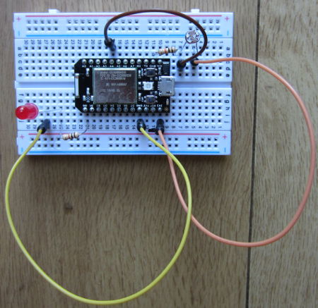
Spark Core is supplied with its own prototyping breadboard. We connected a light dependent resistor (LDR) to one of the regulated 3.3V output pins, and to one of the ground pins via a 10K resistor. This creates a voltage divider (where the LDR meets the resistor), the output of which we connected to analog pin A4. (In the photograph above, we also have an LED connected via a current limiting resistor to digital pin D0).

The analog pins on the Spark Core are 12-bit analog to digital converters (ADC). Therefore, they measure the voltage on the pin and give it a proportional digital value from 0 to 4095 where 0 is 0V and 4095 is 3.3V.

const int ldrpin = A4;
int lightlevel = 0;

void setup(){
   pinMode(ldrpin, INPUT);
   Spark.variable("lightlevel", &lightlevel, INT);
}

void loop(){
   lightlevel = analogRead(ldrpin);
}

Above is the Wiring code we wrote to continuously save the digital conversion of the measured voltage on pin A4 (here called ldrpin), as a variable lightlevel. Defining the Spark.variable lightlevel in setup makes it accessible via the Spark servers.

With that code flashed to the Spark Core and running, you can now instruct the Spark servers to grab that variable (with the Spark API). The simplest way to grab the lightlevel variable is to enter a URL in your web browser like this:

https://api.spark.io/v1/devices/YOURDEVICEID/lightlevel?access_token=YOURACCESSCODE

…obviously substituting in the device ID and access code for your own Spark Core. The browser will then display something like this:

{
  "cmd": "VarReturn",
  "name": "lightlevel",
  "result": 2961,
  "coreInfo": {
    "last_app": "",
    "last_heard": "2014-08-03T11:21:32.577Z",
    "connected": true,
    "deviceID": "YOURDEVICEID"
  }
}

So, in this example the light level was measured by the Spark Core to be 2961 (meaning that the voltage on the pin was 3.3*(2961/4095) Volts).

Instead of measuring a light level, we could have connected any other digital or analog sensors – temperature sensors for example – pre-processed the collected data on the Spark Core board to be saved as useful values which we could view from anywhere in the world.

For a final test, we wrote a very short Python script on an internet connected Raspberry Pi to grab just the value of lightlevel out of the file returned by Spark and to print it out.

#!/usr/bin/python
import urllib2
import json
response = urllib2.urlopen('https://api.spark.io/v1/devices/YOURDEVICEID/lightlevel?access_token=YOURACCESSCODE
html = response.read()
reading = json.loads(html)
lightlevel = reading['result']
print lightlevel

This was saved as file core.py and run using the command sudo python core.py in the terminal. In under one second, the value of the light level measured on the Spark Core was displayed. With a slightly more complex Python script or using cron the light level could be checked every 5 minutes or other interval and logged to a file for later analysis etc.

All in all, first impressions of Spark Core are very favourable. While we have previously used ethernet shields with Arduino to enable remote control and monitoring over the internet, this has necessitated messing around with broadband router settings and firewalls etc. With Spark Core everything happens automagically which makes things a lot simpler for the average user and opens up many Internet of Things possibilities.

Click here to visit the Spark.io website for more information about Spark Core.
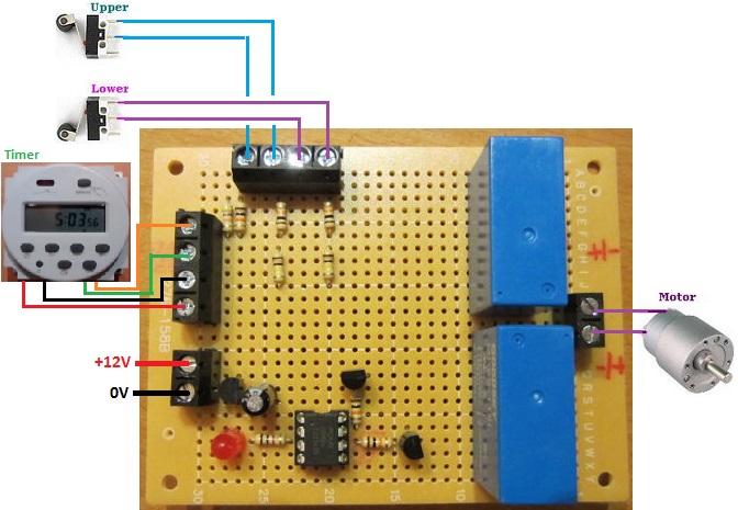
Solar Pump Controller with Timer Override

In our blog post Solar Water Heating Pump Controller with LCD we showed a controller which incorporated a timer override so that the user could force the pump of their solar water heating controller to run at certain times of day or night – for example in the winter to protect against frost, or for any other reason.

This has proved to be quite a popular added feature, so we can now also offer it on request to our 2014 Solar Water Heating Pump Controller with LCD.

Override solar water heating pump controller with a digital programmable timerThe controller works exactly per the standard 2014 controller, just with a pair of added screw in terminals to which a manual switch or suitable programmable timer switch can be connected for more control.

If you require a solar water heating pump controller with this added feature, please email neil@reuk.co.uk with details of your requirements.

Nabduino Remote Access Board

Pictured below is Nabduino – an “open source peer-to-peer remote access embedded board with a user modifiable web-interface developed by Nabto“.

Nabduino board

This small board (available to purchase here: buy Nabduino) can be accessed via a direct encrypted connection through a firewall without the need to change the firewall settings of your router.

If for example you set up a server on a Raspberry Pi – that server will only be visible on your local network unless you change settings on your router to make it visible world wide. If your that server is not set up correctly, then your whole network is at risk – therefore this is best left to experts. Having set up that server, you then need either a static IP address (not usually free of charge) or set up some web services (sometimes free, sometimes not), so that you can find your server when you are outside the local network.

The Nabduino board makes things a lot easier and safer than all that trouble. You simply connect an ethernet cable connected to your local network to the board, connect power to the board, and that is it. Each Nabduino board has a unique ID, and there is a simple web interface which gives you access to the board and its sensors etc accessible from anywhere in the world at XXXX.nabduino.net where XXXX is the ID of your board.

web interface for nabduino board

Via the simple web interface (pictured above), the state of the on board button can be viewed, an on board LED can be controlled, the temperature of the microprocessor can be monitored, five PWM outputs can be set with values from 0-255 for dimming lights or motor control, the status of six analog inputs can be viewed, and thirteen digital pins can be set to input or output and be controlled remotely.

As it stands, Nabduino could be used for simple remote control of a home via relays connected to digital outputs – for example, turning on some lights when you are away from home using your mobile phone or PC. Similarly, very basic home monitoring could be achieved with sensor switches connected to digital inputs. However, much more powerful things can be achieved connecting the Nabduino to an Arduino board so that the Arduino can respond to digital and PWM signals from the Nabduino and carry out any complex logic.

We will be looking at the Nabduino board in much more detail soon. Until then, click here to find out more about Nabto.com.