The Cost of the Move to Biomass

There is an article in this weeks Economist which looks at the potential downside of the EU’s move toward Biomass as a means to reach its target of generating 20% of its power by renewable energy.

EU planners want 1210 Terawatt hours (TWh) of energy to come from biomass by 2020 (compared to 500 TWh from wind power). The majority of that biomass will be used to heat things – primarily in domestic wood burning stoves and boilers in Eastern Europe, but there will still be more electricity generated by burning the remaining 20% of the biomass than from all solar and offshore wind turbine generation.

While some of the biomass will come from crop residues and other waste products, the majority will be from wood – trees from sustainable forestry.

Biomass for electricity generation

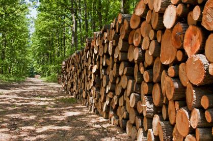
While this is seen as being carbon neutral – plant a tree, it absorbs carbon, burn that tree, it releases the carbon, plant a new tree, and so on, in reality this is not the whole story. Biomass power stations need fuel, and large power stations need a lot of fuel – far more than can be sourced locally. Therefore huge volumes of biomass material need to be processed (using electricity – probably not renewably generated) and moved hundreds or even thousands of miles from forest to power station (most likely using diesel).

3.3 square kilometres of forest per 1MW of output from a biomass power station, so huge swathes of biodiverse natural ecosystems are likely to be displaced by unnatural plantations with the loss of wildlife habitats and other environmental issues.

Natural woodland ecosystem

The Economist’s argument is that with all these problems, public money should not be spent on biomass subsidies which distort the market, and instead ‘the market’ should be left to choose the cheapest and cleanest renewable technology (and to invest in future renewable technologies) by setting a carbon tax which makes fossil fuels more expensive to use.

Autonomous Robot Solar Panel Cleaner

With huge growth in solar electricity generation in North Africa and the Middle East recently a problem keep recurring – how to keep solar PV panels clean in arid regions with virtually no rainfall and lots of dust. A sandstorm can cover panels with a layer of dust in minutes which will reduce their efficiency by 80-90%.

One way around this problem is to use the some of the solar electricity generated to run a desalination plant to get fresh water to clean the panels, but this is very inefficient and expensive, and requires the solar array to be installed near the sea.

Wall Walker cleaning robot

Miraikikai Inc have an existing commercial product called WallWalker (pictured above) which is an robot wall and window cleaner. It is primarily designed to be used to clean inaccessible windows adhering to them using suction and zig zagging its way up and across them while cleaning.

Miraikikai solar panel cleaning robot

Pictured above is their new prototype automomous solar panel cleaning robot developed in conjunction with researchers at Kagawa University. It weighs in at around 11 kg and has a battery life of two hours.  Its rotating brush cleans the solar panels as it passes over them without using any water.

It is hoped that a commercial version of this prototype will be ready for sale by this time next year (spring 2014) ready to meet demand.

Swansea Bay Tidal Lagoon – Tidal Power

The UK is blessed with the second highest tidal range in the world. Having such a big vertical difference between high tide and low tide makes tidal power an attractive and realistic renewable option.

The Bristol Channel between England and Wales acts as a funnel resulting in the typical 0.6 metre tidal range of the ocean increasing to 9 metres. For this reason for decades their have been plans to build the Severn Barrage – a 10 mile dam between England and Wales which could provide an average of 2GW of power.

While the Severn Barrage has never been built because of the environmental impact and financial costs, a public consultation is about to start for the proposed Swansea Bay Lagoon – a 9.5km long wall 11 metres above the low tide enclosing 9.4km2 of water around Swansea Bay, Wales.

Proposed Swansea Bay Lagoon - tidal power

200-250MW of low head bulb turbines of the type used successfully in La Rance Tidal Power Plant in France would generate electricity as the sea enters the lagoon on the rising tide, and leaves the lagoon on the falling tide. This would generate 400 GWh of electricity per year which is equivalent to the domestic consumption of the whole of Swansea (107,000 homes), and would cut carbon emissions by 200,000 tonnes per year.

Tidal turbines at Swansea tidal lagoon

The design life for the lagoon is 120 years meaning 120 years of reliable and wholly predictable tidal electricity generation. It would be the first man made tidal lagoon in the world.

Causeway at proposed swansea bay lagoon

The predicted cost of the Swansea Tidal Lagoon and associated development and infrastructure is £650 million. It would take 2 years to build the wall and if given approval, this tidal power station could go online as early as 2017.

For more information click here to visit the official Swansea Bay Tidal Lagoon website.

9V from 12V Regulator Module – Alternative to L7809

About six months ago a Chinese company on eBay had a special offer selling the item pictured below for US$2 each. We bought five and put them somewhere safe and then forgot what they were for.

L7809 alternative - high current 4 Amps 9V output regulatorA quick test today showed them to be efficient 9V from 12V regulators working much the same as the common L7809 regulator.

With a bit of searching around we finally found the details for this product. It is an high current voltage regulator which takes an input voltage of from 12-23 VDC and outputs 9 VDC. No heat sinking is required up to a constant 2.5 Amps of output current, and they are rated to supply brief peaks of up to 4 Amps.

9V from 12V regulator module - 4 Amps

The pin connections (the three legs) have 2.54 mm (0.1 inch) pitch exactly the same as for the L7809 regulator, and the device is also of similar overall dimensions. Therefore, this little PCB can be used to substitute an L7809 (pictured below) where more current than the 1-1.5 Amps (with heat sink) maximum of the L7809 is required.

L7809 voltage regulator


It could for example also be used instead of the LM317T we use in our standard 9V from 12V regulator (though we have designed that with R1 = 330, R2 = 2K8 so that we get an output of around 8.8V compared to the 9.3V this regulator module outputs – a lower voltage to reduce power consumption for renewable energy powered applications). With thicker cables for the connections this would give a 2.5 Amp constant current 9V from 12V regulator with no need for heat sinking.

This module has a small integrated circuit labelled MP2307DN which a quick search on Google shows up as a 3A constant load current DC-DC step-down power supply module and a monolithic synchronous buck regulatorwhich has been used in this case to provide a 9V output.

At the time of writing we can only find this device here: L7809 Alternative Module priced at US$4.99 plus US$1.99 for air mail delivery. (The same vendor also has similar L7812 and L7833 alternative modules for 12V and 3.3V outputs respectively.)

Project PCB Boards for 18-pin PIC Microcontrollers

We use microcontrollers every day for many of our projects, mostly 8-pin but quite often 18-pin for the more complex products we are requested to design and build. We have found the following products to be particularly helpful for prototyping and for one-off projects – 18-pin project PCBs from UK company RK Education.

RKP18HP 18 pin PIC PCB with power transistors

Pictured above is a RKP18HP board designed for use with 18-pin microcontroller such as PICAXE. This board gives 5 inputs, and 8 TIP121 power transistor outputs for high power applications. It is supplied with a software download socket to get your code onto your microcontroller.

Below is the RKP18Relay8 board which is again designed for 18-pin microcontrollers and takes up to 5 inputs and controls 8 SPDT relays each with LED indicators to show then they are energised. Again the software download socket is provided.

RKP18Realy8 18-pin 8 SPDT relay PCB

These items are available as just boards (PCB) or as full kits and are very competitively priced – transistor board £1.19, kit £3.49; relay board £2.00, kit £10.99. The kit prices include all the components shown – e.g. all the relays, screw in terminals, LEDs, resistors, etc, so all you need to add is your choice of 18-pin microcontroller and you need some solder and a soldering iron.

The power transistor board takes about 10-15 minutes to solder together, and the relay board around 15-20 minutes. Full instructions are provided and the PCBs are well labelled so it is difficult to make any mistakes.

picaxe 40x2 microcontroller

Many other boards are also available for low power applications, smaller and larger microcontrollers, and much more. For a one off 28-pin or 40-pin microcontroller project (e.g. PICAXE 40X2 as pictured above) the corresponding boards with large prototyping areas are particularly useful.

Take a look at the RK Education website here.

Are Prices of Solar Panels Going to Stop Falling or Even Rise?

The prices of photovoltaic solar panels (PV) have been falling consistently for years, and particularly for the last couple of years. The success of generous feed in tariffs in Germany first and subsequently in the UK amongst other countries greatly increased the demand for PV solar panels, demand which was rapidly met by new Chinese manufacturers.

Suntech solar panels

Thanks to large government subsidies solar panel manufacturing boomed in China with companies such as Yingli and Suntech selling more and more PV panels at lower and lower prices grabbing well over three-quarters of the world solar market. Panel prices are now a quarter what they were in 2007/8. Global manufacturing capacity is now over 60 Gigawatts per year, but demand in 2013 is predicted to be half that at just 25-30 Gigawatts.

Subsidised over-production resulted in panels effectively being sold at a loss and now many of China’s 500+ solar module manufacturers are deep in debt and facing bankruptcy with no sign of a bail out from the government. It is likely that there will be many business closures, consolidation, and reductions in supply in the coming months and years as the market adjusts itself.

At the same time commercialisation of new technologies which offer more efficient solar panels which can be made more efficiently, more cheaply (with future economies of scale) and with less damage to the environment has been delayed because consumers’ demand has been met with the (unsustainably) cheap conventional silicon PV modules.

Even with the latest manufacturing processes, cheap labour, and government subsidies, existing technology solar PV is still more expensive than fossil fuels. Until there is commercialisation of more advanced solar PV technology we will not see PV compete on a level playing field (i.e. without subsidies) and beat fossil fuels on price.

GE thin film photovoltaic solar panels

Therefore although in the short term we can expect solar module prices to level or even rise a little, this will finally open the door to the commercialisation of new technologies currently waiting in the wings (e.g. thin-filmsolar panels) which in the medium/long term will finally give us economically sustainably low-priced fossil fuel beating panels.

Project of the Day – 24V Low Voltage Disconnect

Pictured below is one of our standard programmable 12V low voltage disconnect (LVD) circuits which has been modified for 24V battery systems.

24V low voltage disconnect - LVD

The base circuit board used is one we designed and have made for us which is a multi-use board with a high quality matching enclosure. By soldering a few jumper links on the back of the board we can change its functionality, inputs, and outputs so that it meets the requirements of whatever project we are working on. We designed the board with a small prototyping area in the middle to which additional components can be added if required.

In order to use this board for a 24 Volt low voltage disconnect things were a little tricky as all on board components are designed for 12 Volts. Therefore we first added an LM317T voltage regulator (using R1=330R, R2=2K8 resistor) and screw in terminals for the 24V battery to be connected to. The 11.8V outputted from the regulator was then connected on the underside of the board to the usual 12V input terminals which are now not used.

We then added a voltage divider to reduce the approx 24V input voltage sufficiently so that it can be measured using the analog to digital converter (ADC) on the PICAXE-08M2 microcontroller – we needed less than 5V across the full range of input voltages from the 24V system (e.g. up to at least 30V), and wanted to set this up so that the digital value given when 24.00V is connected to this new LVD is the same as that given when 12.00V is connected to the standard LVD.

The ADC converts the voltage it is seeing into a 10-bit digital value from 0-1023 where 0 will be the value if the voltage is zero, and 1023 will be the value if the voltage is equal to the supply voltage of the microcontroller (5.00V in this case).

With the accurate 470K/100K voltage divider we use on the standard 12V LVD we get 35.922 per Volt – i.e. input 12.00V to the circuit, the voltage divider will reduce this before it gets to the ADC (to 2.553V) and the ADC will output 12.00*35.922 = 431. We have hard-coded the 35.922 multiplication factor into our 12V LVD and everything else is worked out from it.

We hand-calibrated the new voltage divider (because the resistors we used in it only have a 10% tolerance). We simply inputted a 24.00V voltage and measured the voltage seen on the ADC pin with an accurate multimeter. DIviding this voltage by 5.00V and multiplying by 1023 to get the ADC value we got 398, less than the 431 it would have been if the resistors were high tolerance. Dividing 398 by 12V we found that the multiplication factor for our 24V LVD was 33.135 per Volt, so we simply changed that one value in the microcontroller code and everything worked perfectly – the only difference is that the user can set the cut in and cut out voltages in 0.2V steps now instead of 0.1V steps.

Project of the Day – Warning Watch Timer for Solo Sailor

Today we made the yacht watch timer pictured below. It was ordered by a solo sailor to use to ensure that she does not fall asleep for too long while on watch (checking the horizon for potential dangers).

Timer to keep solo sailor awake

As this is such a vital piece of equipment, we actually put two independent timers onto the same circuit board doubling up on all components including the warning buzzers. Therefore if a component on one of the timers fails, the second timer will continue to work perfectly.

The user can set the number of minutes the timers are to run before the warning piezo buzzers sound – e.g. 5, 10, 15, 20..etc minutes. Timer-2 is then automatically set to run for one minute longer than Timer-1.

While the device is connected to the 12VDC system on board, a pair of panel mounted LEDs flash once every second to show that the timer is running. Each time the sailor checks the horizon they press a panel mounted button to restart the timer countdown.

push to make reset button for timer

If the sailor falls asleep or forgets to keep watch then when the timer has run down Timer-1’s buzzer will sound for one minute. (We left the protective sticker over this buzzer to keep the sound level down.) If the sailor still does not press the button during that minute, then Timer-2’s buzzer will start to sound very loud and continue to sound until the button is pressed.

The sailor will fit an ON/OFF switch before the timer device. Each time it is switched on, both LEDs will light up and the two buzzers will sound for one second to confirm that everything is working as it should. The programmed number of minutes for the timer are stored in memory and are not lost when power to the device is disconnected.

The timers are built using Picaxe-08M2 microcontroller chips each powered via its own 5V regulator. The device is fitted with reverse polarity protection.


REUK Have a New (Old) Camera

REUK finally have a new (old) camera with excellent macro functionality – the Canon IXUS 220HS. Expect better photographs on the REUK.co.uk website – particularly close-ups of elecronics.

macro-lens-testing-reuk

This camera first came out in 2011 offering a 12.1 megapixel sensor, 5x optical zoom, and full-HD video recording, priced at around £200. It is now available new for around £100 and used from just £40.

macro-lens-testing-zoom-reuk

We are certainly very happy with it so far. It really pays to buy high quality electronic devices a couple of years after their release to know for sure what you are getting, that it has all the functionality you need, and to get it at a great price.

Project of the Day – Dawn / Dusk Raspberry Pi Switch on Device

Pictured below is a device designed to switch on a Raspberry Pi for a user programmable number of minutes at dawn and dusk as detected by a light detector. Under normal circumstances the Raspberry Pi itself could be used to detected day and night, but although the Pi is a very very low powered computer (2.5 Watts), that is a relatively large amount of power if it is to be on continuously 24 hours per day powered by a solar charged battery, as was our customer’s requirement.

dawn and dusk detecting controller to power a Raspberry Pi

Instead of leaving the Raspberry Pi running continuously, this intermediate controller circuit supplies power to the Pi only when required, and draws only a few milliAmps of current rather than hundreds of milliAmps of the Raspberry Pi.

The controller circuit we have built is based around a Picaxe-08M2 microcontroller. The user can set the light level threshold at which dawn and dusk are detected (using similar logic to that successfully used in our dawn dusk relay controller), and the number of minutes that the Raspberry Pi is to be powered at dawn and at dusk.

A MOSFET is used to supply a 12V output at dawn and dusk which passes through the 5V from 12V regulator pictured below to supply the required 5 Volts DC to the Raspberry Pi.

5-volt-regulator-for-raspberry-pi

Normally we would fit voltage regulation directly on our circuit board, but it is not possible to buy even half the components on this ready made 3 Amp rated 90% efficient 3.3V / 5V from 12V regulator (priced at £1.12 including delivery) so we used that. We just soldered 12V+, 12V-, and 5V+ leads to the regulator, and screw-in connectors on the output side of our controller to hook it up. A couple of terminals on our board then supply the regulated 5V voltage to the Raspberry Pi at dawn and dusk.

This will be put to use in a hen house door controller. The Raspberry Pi, extended with a Gertboard attached to the GPIO interface will be used to control a motor which will open/close a horizontally sliding door. Microswitches will be used to detect when the door is fully open/closed, and the Raspberry Pi will give feedback to the user by sending him an email. A camera may also be added to the setup in the future.