Raspberry Pi GPIO with BerryIO

Today we have been trying out BerryIO – a control system for Raspberry Pi which is web browser based for ease of use and set up.

Although BerryIO can be used to monitor the system status of a Raspberry Pi; of most interest to use was the ability to easily control GPIO without any need for programming experience. This makes home automation via mobile phone, tablet, or desktop PC a realistic option even for relatively basic users.

Installation is achieved by entering the following commands at the prompt:

wget -N https://raw.github.com/NeonHorizon/berryio/master/scripts/berryio_install.sh
chmod +x berryio_install.sh
sudo ./berryio_install.sh

followed by:

berryio help

just to make sure it is working.

With BerryIO installed on your Raspberry Pi, you simply enter the IP address of the Raspberry Pi in the web browser on your phone, tablet, or PC, and after entering your Pi username and password when prompted you get a menu of options of which we found GPIO, camera (if you have one), and system status to be the most useful.

Raspberry Pi BerryIO - GPIO Control
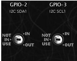
Selecting GPIO from the menu, all of the GPIO pins are shown and you can set them individually to be either NOT IN USE, IN (for inputs), or OUT (for outputs).

BerryIO GPIO inputs Raspberry Pi
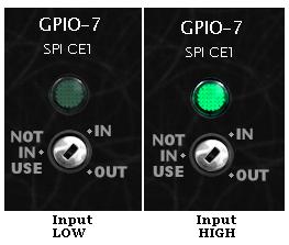
If you select IN for a pin (for example GPIO-7) as shown above, when a high signal arrives on GPIO-7 the green light turns on, and when the signal arriving is low, the green light is turned off. The web browser updates the status of the GPIO pins in real time – therefore no need to refresh the browser for updates.

Raspberry Pi GPIO outputs controlled from web browser BerryIO
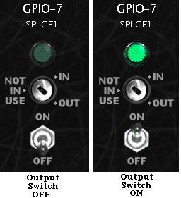
If you instead select OUT for a pin, a toggle switch appears below the selector. Click on ON to turn on the output (green light illuminates for that GPIO pin in the browser), or click OFF to turn off the output (green light turned off).

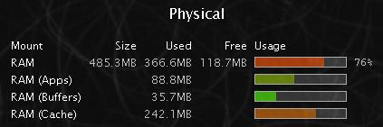
The system status shows a few bits and pieces of information about memory, storage, loads etc, but this does not currently update in realtime so you have to refresh the browser for the latest data.

raspberry pi system status - BerryIO

We will be looking into some useful real world useful applications for BerryIO, but it is certainly well worth installing it and having a play around with it just for fun.

BerryIO is still under development and new features and functionality are still being added to it. The release of an API for mobile app development should hopefully result in some interesting and useful tools being developed to control the Raspberry Pi remotely via a simple user interface.

Full details of BerryIO and the installation instructions are available here: install BerryIO.

12V Programmable PIR Timer with Override

Pictured below is a modified version of our standard 12V Programmable PIR Timer with 3A Output.

pir motion sensor timer controller with override

The standard version turns on an output after motion has been detected, and keeps the output on until a user programmed time has elapsed.

This new version retains all the same functionality as the original, but has the addition of a pair of screw in terminals into which the contacts for an external push to make button can be connected.

The software on the microcontroller has been modified for this version to provide manual override functionality. If the output is off (because no motion has been detected), pressing the override button (for more than half a second) turns on the output and the red LED flickers constantly.

To cancel the manual override, the override button is again pressed for more than half a second which turns off the output.

If the override button is pressed while the output is already on (from a recent motion detection event), then the output will be turn off.

If you need any type of PIR sensor linked timer/controller, email neil@reuk.co.uk with details of your exact requirements.

Arduino SD Card Datalogging

We recently published our Arduino Solar Water Heating Pump Controller Design and Code which shows the basics of putting together a very simple solar water heating pump controller which you can then extend to add the other features you require. (Click here also for our Introduction to Arduino.)

The feature about which we have received the most questions is datalogging functionality to generate a log file of the temperatures recorded and the status of the pump (on or off).

Arduino SD card temperature datalogger

Pictured above is a demonstration on prototyping breadboard of how datalogging can be achieved using an Arduino SD Card Module (click link to buy). These are available from just £0.99 including delivery for standard SD cards (and from around £1.60 including delivery for modules for micro SD cards).

Arduino SD card reader moduleSD card modules for Arduino are very simple to use. SD cards operate on 3.3V, but the Arduino on 5V; however, these modules have all the necessary components fitted to bring down the voltages and enable safe reliable operation without the need for you to add any external components.

In the breadboard demonstration above, we have a single LM335 temperature sensor connected to the A0 pin of an Arduino Nano as per the solar water heating pump controller design (linked to at the start of this post).

We then have the following connections between the Arduino and the SD Card module:
Arduino D10 to SS (slave select)
Arduino D11 to MOSI (master out slave in)
Arduino D12 to MISO (master in slave out)
Arduino D13 to SCK (serial clock)
We also connected the 5V and GND pins of the Arduino to the corresponding SD Card module connections to power it.

Note that some SD Card modules have their connections labelled differently.
CS=SS, DI=MOSI, DO=MISO, and CLK=SCK.

For this demonstration we just want to create a text file (called templog.txt), measure the temperature once per second, and add each temperature reading to the end of the file to form a very basic datalog.

Arduino temperature datalogger sd cardThe stored data on the SD card can then be viewed, manipulated, and graphed on a PC. Multiple temperature sensors (or other sensor inputs) can be added and logged by extending the bare bones Arduino code above.

arduino rtc real time clock module

For a more advanced datalogger, the next key element to add is an RTC (real time clock). Using an RTC each data point can be logged alongside the exact time that it was recorded. Arduino RTC modules including a backup rechargeable button cell are available very cheaply. We will show you how add an RTC to an Arduino datalogger in a future post.

Automatic Horse Feeder Controller

Pictured below is a controller for an automatic horse feeder. This device is made up of a 12V digital programmable timer, a microcontroller board, and an eight relay board.

automatic horse feeder

The horse feeder hardware comprises four shelves onto which the owner can put feed. Four car door locks are used to release the shelves one at a time to release the feed and drop it down to where the horses can access it.

When 12V at one polarity is supplied to a lock, it will perform a pull action; when the polarity is reversed it will perform a push action (which resets the lock ready for the next time it is to be used).

automatic horse feeder control board

The programmable digital timer is set by the end user to turn ON for one minute at the times of day that the horses need to be fed. Our controller (pictured above) receives power when the timer is ON, decides which feeder should be released next, pulls the corresponding lock to release the feed shelf, waits a couple of seconds, and then pushes the lock to reset the feeder.

To enable the polarity supplied to the locks to be reversed, eight SPDT relays are used for which we used a commercial relay board (click here to buy relay boards of this type). We connect 0V to all the relay NC’s, and +12V to all the relay NO’s, then for each pair of relays, we connect the COM’s to the lock power inputs.

automatic horse feeder relay board connectionsIf we close one relay in a pair we get one polarity supplied to the lock (since it sees +12V and 0V), and we we close the other relay, we get the other polarity (since it now sees 0V and +12V).

underside of automatic horse feeder relay boardIf you have a process to automate in a way similar to this example, email neil@reuk.co.uk with details of your exact requirements.

Automatic Car Windscreen Heater Timer

Pictured below is our timer for an after market car windscreen heater – in this particular example, for a Land Rover.

car windscreen heater prototype connection diagramThe biggest seller of after market heated windscreens in the UK is Ricky Evans Motorsport. (Click here for the relevant heated windscreen wiring diagram.)

The relay output from our programmable timer fits into the wiring in place of the standard on/off switch. The timer can be programmed by the driver to turn on the heated windscreen for from 1-20 minutes after the button (which can be mounted in the dash) is pressed. A panel mountable LED is provided to show when the heater is on.

Automating windscreen heating in this way prevents the heater from being left on unnecessarily long.

The exact button and LED can be substituted with whatever switchgear and indication lighting matches the vehicle in which the system is installed.

If you need one of these car windscreen heater timers, email neil@reuk.co.uk with details of your exact requirements.

PICAXE Arithmetic Problems

Hitting the maximum number limit with PICAXE microcontrollers

In a recent post we showed our 24V Low Voltage Disconnect with Data Display. This device monitors and logs the voltage of a 24V battery bank, disconnects the output loads if that voltage is too low to protect the batteries, and has an LCD display on which the last 100 days of battery voltages can be checked, summarised, and the maximum and minimum recorded voltages displayed for analysis.

This device is built around a PICAXE microcontroller. These are simple to use and quick to programme microcontrollers, but they have a few ‘features’ which can make life difficult (sometimes making an Arduino a far better alternative). PICAXE chips can only process numbers in the range 0-65535, they cannot process negative numbers, and cannot process floating point (decimal) numbers.

In most cases those limitations are not an issue, but with our 24V LVD for example it was. The microcontroller is powered via a 5V regulator. In order to measure incoming voltages over 5V, a voltage divider (Wikipedia) is required – a pair of resistors connected in series with one end connected to the incoming voltage to be measured and the other end to 0V. The values of the resistors are chosen so that the voltage measured where the two resistors meet is in the range 0-5V across the full range of likely input voltages.

For our standard 12V low voltage disconnects we use a 47K resistor for R1 and a 10K for R2. The voltage output from this voltage divider is equal to R2/(R1+R2) multiplied by in the input voltage. So, if the input voltage is 13.00V for example, the voltage divider output voltage will be 13*(10K/(10K+47K))=2.281V which the 10-bit ADC on the PICAXE will see as (2.281V/5V)*1023=467. Only when the input voltage exceeds 28.5V will the voltage from this voltage divider exceed 5V, and 28.5V is never going to be seen from a 12V battery.

With our 24V datalogging LVD we chose 68K for R1 and 10K for R2. This gave an input voltage range of 0-39V corresponding to the ADC range of 0-1023 which is perfect for a 24V battery system. However, we hit upon a problem.

We work out what an input voltage of 1V corresponds to as an ADC value after passing through the voltage divider. With the 68K/10K divider on our 24V LVD, 1V on the input corresponds to an output of 0.12821V which corresponds to (0.12821/5)*1023=26.23. Therefore, if we divide the ADC value on the microcontroller by 26.23, we calculate the input voltage.

BUT, the PICAXE chip can only do integer arithmetic. An ADC value of 415 in this example corresponds to a measured input voltage of 415/26.23=15.8216V, but with integer arithmetic 417/26=15V so off by almost a full Volt.

In order to retain resolution and accuracy while forced to use integer arithmetic, we multiply the ADC reading by 100 and divide it by ten times the per volt ADC value. The result given is ten times the input voltage – for example (415*100)/262=158 which means 15.8V which is close enough to the actual value.

But, this approach can then lead to another problem. In the case of our 24V LVD with the 68K/10K voltage divider, when the input voltage exceeds just below 25V (which will almost always be the case with a maintained 24V battery bank), the ADC value is greater than 656. When we multiply this ADC value by 100 we get a number of over 65600 which the PICAXE (with its maximum number limit of 65535) cannot process. For example it will see 65536 as 0, 65537 as 1, 65538 as 2, and so on and will think that an input voltage of 25V is less than 1V which is not much use.

There are many (very complicated) ways around this maximum number problem using variables and/or the EEPROM to store parts of large numbers while doing calculations, but in the case of the 24V LVD with datalogger, all the internal data EEPROM was dedicated to datalogging, and all the variables were already being used. Therefore, instead of multiplying the ADC value by 100 and dividing it by ten times the per Volt ADC value, we modified our code to multiply the ADC value by 50 and divide it by five times the per Volt ADC value. This results in a small loss of accuracy of less than 0.1V at the upper range of predicted voltages, but works well enough for this particular device.

So, when choosing a voltage divider for an accurate voltage measuring device with a PICAXE chip, choose the resistors to ensure that the full possible input voltage range is more than covered, and also that any multiplication of ADC values in order to maintain resolution with integer arithmetic does not generate numbers over 65535. (Alternatively just use an Arduino with floating point arithmetic!)

Solar Water Heating Pump Controller for Hot Tub with Maximum Temperature

Pictured below is another of our solar water heating pump controller variations. Again based on our 2013 solar water heating pump controller with relay, this controller is modified to use digital waterproof temperature sensors (ds18b20), and also to have a user programmable temperature limit.

waterproof-ds18b20-2013-solar-controllerThis controller is designed to be used with solar heated hot tubs and jacuzzis. As the volume of water in a hot tub is relatively small (compared to swimming pools for example) it is possible for the water in the tub to become unpleasantly or even dangerously hot after an extended period of sunshine.

This controller has been modified to have a user programmable maximum temperature. When the temperature of the water in the hot tub reaches this maximum, the pump will turn off and stay off until the hot tub temperature has dropped by at least 2 degrees Celcius.

Programming the maximum temperature is simply the matter of holding the button to enter programming mode at start up, then pressing it X times where 20 + 2*X is the desired maximum. For example, 8 presses for a 36 degree Celcius maximum.

If you need a solar water heating pump controller for a domestic system, swimming pool, or hot tub, with or without an LCD display, email neil@reuk.co.uk with details of your exact requirements.

Playhouse Lighting Controller with LVD

Pictured below is the connection diagram for a controller we have built to be used in a child’s playhouse. The playhouse will have a solar charged battery which will be used to supply power to three LED spotlights with a light switch, a small fan to circulate air and prevent the playhouse getting damp or too hot, and a dual cigar lighter socket with USB sockets which will be used to charge battery powered gadgets.

Connections for low voltage disconnect with twin outputs - regulated for LED lighting and to power a fan for ventilationAs the playhouse will be used by children, safeguards have been fitted to prevent the battery from becoming excessively depleted and permanently damaged.

In order to prevent the lights being left on and forgotten, when the light switch is turned on, a timer starts and if after one hour the light switch has not been turned off, the lights turn off automatically and will not turn back on until the light switch is toggled.

The output from the controller to the LED lighting is regulated to 12.0V so that excessive voltage (particularly when the batteries are being charged) does not damage the voltage sensitive bulbs.

To reduce power consumption, the fan which is used to ventilate the playhouse is turned on for just one hour every six hours automatically by the controller. The output to the fan is not regulated as the fan is rated for use with up to 18V, and if the battery voltage is high it is because there is or has been a lot of sunshine. Therefore the faster fan speed will prevent the playhouse getting too hot and stuffy.

In order to prevent the battery from running too low on charge, an automatic low voltage disconnect is incorporated. When the battery voltage falls below 11.9V, the outputs to the fan and lighting turn off, and only turn back on again when the measured battery voltage exceeds 12.4V.

The cigar lighter / USB socket is connected directly to the battery as the gadgets being charged by it will not draw much current for long if left connected since their batteries will get full and charging will stop automatically.

If you need a controller such as this, or with any of the features it has, email neil@reuk.co.uk with details of your exact requirements.

Simple Low Voltage Disconnect with Two Outputs

Pictured below is a low voltage disconnect circuit with two outputs.

low voltage disconnect (LVD) with two outputs to share the loadWe make a basic low voltage disconnect (LVD) designed specifically for use with low voltage LED lighting which incorporates a low-dropout 12V regulator. This device ensures that:

  • the battery does not get damaged by running too low on charge. If the measured voltage falls below 11.9V the output loads are switched off and not switched on again until the voltage is measured to be 12.5V or above.
  • the LED lighting is not damaged by excessive voltage (>13V) – particularly important with solar powered lighting systems where battery voltage can get up to 15V.

The pictured LVD/regulator is different in that it has dual outputs. The LM2940CT-12 voltage regulator is limited to around 1 Amp of output load, so our standard unit is not suitable in cases where the total LED lighting load exceeds around 8-10 Watts. Where the total load is more than around 2 Amps, we use an LT1084CP-12 regulator on the output side, but these are very expensive. Therefore where the LED lighting load is around 10-18 Watts, and can be split into a pair of separate lighting circuits, we simply make a double output regulator and split the load.

If you need something along these lines, email neil@reuk.co.uk with details of your requirements.