GertDuino has Arrived

Today our GertDuino board arrived. Here are a couple of photographs of GertDuino. First of all the whole board.gertduino raspberry pi board

and then a zoomed in image of the user buttons B0 and B1 and LEDs D5-D10 which should prove to be very useful when making prototypes as they can be used to show system status and to accept user inputs without the need for any external components.

gertduino leds and buttons

We have some projects in the pipeline for which the GertDuino / Raspberry Pi combination will be perfect, so we will have some detailed articles on GertDuino very soon on the main REUK.co.uk website.

GertDuino for Raspberry Pi

GertDuino board to expand Raspberry Pi

Pictured above is the new GertDuino board, developed by Gert van Loo – inventor of the popular Raspberry Pi add-on (GPIO extension) Gert Board.

The GertDuino is designed as a Raspberry Pi add-on, and gives the best of both worlds – the low power consumption and many input/output options of Arduino with the processing power and connectivity of the Raspberry Pi.

Gertduino board mounted to Raspberry PiThe image above shows the GertDuino connected to the Raspberry Pi.

The GertDuino is based around the popular Arduino Uno with a non-surface mounted ATmega328 microcontroller which can be programmed directly from the Raspberry Pi with code written and compiled on the Raspberry Pi. The GertDuino is compatible with all existing Arduino shields (Uno).

Once programmed GertDuino can be used as a standalone board or left coupled to a Raspberry Pi if the project calls for it. When connected to Raspberry Pi, it takes its 5V power supply directly from it, but as a standalone an external 5V power supply is required.

In addition to all the functionality and input/output of the Arduino Uno, a second microcontroller has been added to GertDuino (a surface mounted ATmega48) which gives an IrDA interface to the board (infrared receiver), a real time clock (with battery back up power supply – CR1025 3V button cell, not included – and high precision crystal). There is also an RS232 interface, and a couple of user push buttons and an array of six LEDs. And all this comes at a cost comparable with an original Arduino Uno board at £22.20 inc VAT available from Farnell / Element14.com.

Of most interest to us at REUK is the ability to use the GertDuino and its real time clock to wake up the Raspberry Pi only when it is needed – for example, the GertDuino could be used to monitor battery voltages or a solar water heating system, and turn on the Raspberry Pi for just a few minutes every 12 hours to process and publish the collected data. The overall power consumption of such a system would be far less than keeping the Raspberry Pi active all the time, making it much more economical to run everything from solar power. (See our article Solar Powered Raspberry Pi for details).

The user manual for GertDuino is full of information, schematics, and more on this new Raspberry Pi add-on. Click here to download and view the GertDuino User Manual (30 page PDF).

Arduino Solar Water Heating Pump Controller Design and Code

Following on from our recent blog posts Arduino Solar Water Heating Pump Controller and Arduino Introduction, we have received a few requests for the source code (sketch) and design for a very simple Arduino based solar water heating pump controller.

We thought it would be an interesting exercise to show how just a few components and twenty or so lines of code can be turned into quite an effective controller, so here it is.

REUK.co.uk Arduino simple solar water heating pump controller - Arduino nano

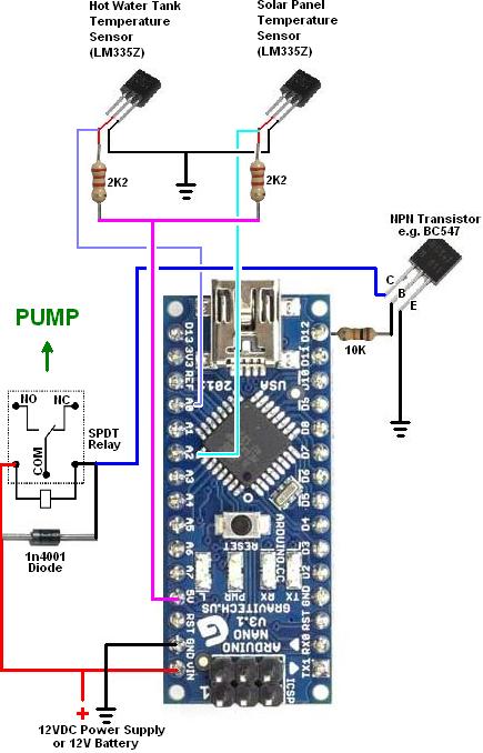
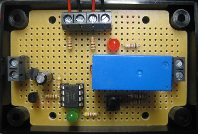
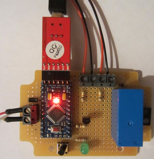
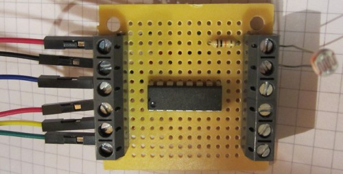
For the schematic (and our own testing) we used an Arduino Nano, but pretty much any Arduino board could have been used. To that we just need to add a couple of LM335Z temperature sensors, a relay, an NPN transistor (we used a BC547), a few resistors, and a diode.

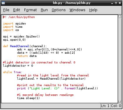
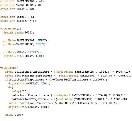
Here is a screenshot of the source code (the link to download it is at the end of this blog post):

Sketch for REUK Arduino simple solar water heating pump controller

This really is about as basic an effective microcontroller based solar water heating pump controller as it is possible to make.

The two temperature sensors connect to the (arbitrarily chosen) A0 and A2 analog pins, and the relay which switches the pump on and off to the D12 digital pin through a transistor (to limit the current drawn from the pin).

The variables diffON and diffOFF are used to set the number of degrees Celcius by which the solar panel must be hotter than the hot water tank for the pump to turn on, and then to turn off respectively. We used 6 degrees for diffON and 3 degrees for diffOFF – you may choose to use different values. These give hysteresis which prevents the pump switching on and off repeatedly and rapidly (since the temperature difference has to fall before the pump is switched off, and then rise before it will be switched on again).

The temperatures are measured every quarter of a second – delay(250) causes the programme to pause for 250 milliseconds. If the solar panel temperature is more than diffON degrees hotter than the hot water tank, the pump will turn on; and then when the temperature difference falls to diffOFF or lower the pump will turn off. And that’s it – simple, but does the job.

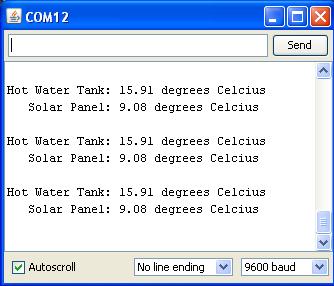
These LM335Z temperature sensors output a voltage of 2.73V + (X * 0.01V) where X is the temperature in degrees Celcius. The analogRead command digitises this analogue voltage to a whole number in the range 0 to 1023 with 0 corresponding to 0.00V and 1023 corresponding to 5.00V.

The calculation done on those analogRead 0-1023 values converts them into temperatures in degrees Kelvin. To convert degrees Kelvin into degrees Celcius you just subtract 273.15. That was unnecessary in this example since we are only interested in the difference between the two temperatures, but if you wanted to display the measured temperatures by connecting the Arduino board via USB to a PC that is how you would get them in Celcius.

Obviously there are a lot of things which can be added to this controller to make it more effective and reliable – e.g. time delays before the pump turns on and off, user programmability, manual override, frost protection, maximum temperature shut off, data logging and processing, and real-time temperature and system status display etc, but this is a good starting off point. There are vast amounts of resources online to help you learn more about Arduino – start with the official Arduino website to find out more.

Click here to download the Arduino source code for the REUK Simple Arduino Solar Water Heating Pump Controller as pictured above.

If you have any questions about the above or if you would like to share your modifications or enhancements to the code or design, please email neil@reuk.co.uk.

Arduino Solar Water Heating Pump Controller

The REUK 2013 Solar Water Heating Pump Controller (pictured above) is one of the most popular products on the REUK.co.uk website. With a temperature sensor on the solar water heating panel, and a second on the hot water tank, this controller decides when to turn the pump on to circulate solar heated water from the panel to the tank.

This controller is based around a PICAXE-08M2 microcontroller which gives a good balance of programmability and simplicity. It does however have one large disadvantage – it can only do integer arithmetic, i.e. performing operations on whole numbers only.

Therefore when we come to make modifications to the controller for particular customer requirements – e.g. frost protection and maximum temperature shut offs etc – things get unnecessarily complicated. Additionally there is limited memory on a PICAXE-08M2 which becomes a serious problem as the complexity of the desired programming increases.

For this reason we are currently porting a lot of our PICAXE based controllers to Arduino which allows floating point arithmetic and far more memory space.

Pictured below is our latest Arduino solar water heating pump controller. It is functionally identical to the standard 2013 PICAXE controller, but offers much more flexibility for modifications and added features.

Arduino pro mini based REUK solar water heating pump controller

The Arduino board used here is the Pro Mini – the smallest of the Arduino range. The red board plugged on to the blue Arduino board in the above photograph is used to connect the Arduino to a PC via USB for programming and/or so that data can be outputted to a serial monitor in real time or for later analysis as shown below where the temperature of the solar panel and of the hot water tank is outputted once every second. If monitoring is not required then this break out board can be removed.

Serial terminal output for arduino solar water heating pump controllerIf you have any particular requirements for a solar water heating pump controller which are not met by our standard controller range, email neil@reuk.co.uk with details of what you need.

If you are interested in building and programming your own solar water heating pump controller as a project, click here for our simple Arduino Solar Water Heating Pump Controller Design and Code which should help you get started.

Analogue Inputs with Raspberry Pi

We have been doing a lot more work with Raspberry Pi over the last few months on some interesting projects which we will soon be covering on the REUK.co.uk website.

Raspberry Pi has an infinite number of uses and offers a great mixture of power, flexibility, and price, but it is lacking in one regard – its GPIO (general purpose input output) does not offer analogue input (ADC – analog digital converter) pins. Therefore it cannot be connected directly to non-digital temperature sensors, light detectors, or measure voltages etc. (This is in comparison to the similarly priced Beaglebone Black which offers seven  12-bit ADC pins for analogue inputs, or Arduino.)

mcp3008 10 bit adc analogue to digital converter 8 channelThere are however simple and relatively cheap ways around this, one of which we will cover here: the MCP3008 10-bit 8 channel ADC pictured above. This is a microchip which can take up to 8 analogue inputs, and communicate their digital equivalent values (0-1023) to the Raspberry Pi via the SPI serial interface.

mcp3008 board to connect to raspberry pi with light detector and other analogue inputs

Pictured above is a small board we have made with the MCP3008 at its centre. Coming in on the left side are six connections to the Raspberry Pi GPIO – 3.3V and GND power connections, and the four connections for the SPI interface.

male to female jumper links for raspberry pi

To make the connections to the GPIO we used male to female jumper links. The female end pushes over a GPIO pin, and the male end goes into a screw in terminal on our MCP3008 board.

raspberry pi GPIO analogue inputs

In order to set up the Raspberry Pi to use the SPI interface there are some commands which are required and you also need to install the SpiDev module. This is all detailed together with connection diagrams in the links to some external resources at the end of this post.

Python code for raspberry pi analogue light detector input

The above shows the simple Python script we used to measure the light level of a light detector connected to our MCP3008 board (making a voltage divider with the light detector and a 10K resistor and feeding the output voltage into channel 0 of the MCP3008 ADC chip. The script simply measures the light level once per second and outputs it to the terminal.

Python light detector on raspberry pi outputThe measured light level is given a digital value from 0-1023. As we wired it, higher values correspond to darker light levels, so the above screen shot shows the results as the light detector was slowly shaded.

Having got the digital value for the analog light level in the Raspberry Pi, you can do anything with it – control lights, detect dawn and dusk, control motorised curtains, log it, view it online and so on. It is also possible to use the exact same technique and MCP3008 to measure a huge range of other analogue signals including temperature sensors, voltage measurement, potentiometers, etc.

Here are links to some useful resources online to find out more information about reading analogue signals with a Raspberry Pi:

Analogue Sensors on the Raspberry Pi Using an MCP3008 – this offers comprehensive details on setting up the Raspberry Pi for SPI as well as connecting it to the MCP3008 and related Python scripts.

Analog Inputs for Raspberry Pi using MCP3008 – a guide from Adafruit.

MCP3008 Datasheet – get a better understanding of the ADC.

Target Controller for Competitive Shooting

Pictured below is a controller we have just made for use in competitive shooting. The competitor has a line of five targets to hit, each of which has a microswitch which closes when the hit target flips over. When each target is hit, an LED lights up, and when all five targets have been hit and all five lights lit, the lights flash on and off five times before the system resets for the next competitor.

Controller for competitive shooting with five targets and five lights which turn on when targets are hit.

We made this as a standalone Arduino project with the ATmega328 microcontroller. This has more than enough IO (input/output) pins to cope with the five inputs (target microswitches) and five outputs (LED lights switched by MOSFETs). The lights are 12VDC powered, so the controller was also made to be powered by 12VDC.

24V Low Voltage Disconnect with Data Display

We have just finished working on a new low voltage disconnect project for a customer who supplies batteries and power inverters to consumers. Quite often his customers make complaints that the batteries have failed after a relatively short period of time, but he had no way of knowing if there was a problem with the battery or (more likely) a problem with the way the battery has been used and cared for.

connection diagram for 24v low voltage disconnect with LCD displayPictured above is the low voltage disconnect with datalogger we made to solve this problem.  The low voltage threshold at which the connected power inverter will be turned off, and the cancellation voltage at which it will be turned back on again can be set before installing the system. A low voltage of 22-24V is likely to be used and a cancellation of voltage of 24-26V for this 24V battery system.

So that the treatment of the batteries can be assessed later, this controller has a built in datalogger. Every 12 hours it records the voltage measured on the connected batteries. Up to 200 data points can be stored in memory for a record of 100 days of activity. If more than 200 are collected then the earlier data points are over-written so that only the most recent 200 are stored.

24V low voltage disconnect with datalogger and display

If/when the system is returned, an LCD display can be connected which enables the 200 data points to be stepped through from most recent to oldest, and a summary is also generated which displays how many times each voltage (from 1V to 35V) was recorded over the last 100 days. Using this data it is possible to see if the batteries were left uncharged for an extended period of time (very harmful to battery life), and how often they were run down to low charge levels (also bad for batteries).

If you need a low voltage disconnect and/or a datalogger, contact neil@reuk.co.uk with details of your specific requirements.

Accurate Programmable Solenoid Timer

Pictured below is a timer which we made today – designed to energise a solenoid valve for a user-programmable duration after the on board button is pressed.

accurate user programmable timer

In our article Making Very Accurate Timers we looked at some ways in which accurate timers can be made – much more accurate than timer circuits based around 4060B counters and 555 ICs for example.

For this timer though since the accuracy required was +/-1 second in five minutes, we just used a microcontroller (PICAXE), making it much easier to set things up to enable user programming of the timer.

The common way to make such a timer is to have it run for a given number of seconds, and repeatedly call pause 1000 which makes the circuit wait for 1000ms (=1 second). The timing accuracy of microcontroller without external clock crystals can be quite poor, but they tend to be consistent.

Therefore to calibrate the timer we simply set it to run for 30 minutes, measured how long it actually took using a stopwatch (which turned out to be 10 seconds less than 30 minutes (so 1790 seconds instead of 1800). As it was therefore fast by 100*(1800/1790)-100 = 0.558%, we increased the 1000ms pause by 0.588% giving 1006 of the microcontroller milliseconds for 1000 real milliseconds. This slowed the timer down a fraction giving it the required accuracy.

For user programming, the button is used to set first the number of minutes the timer is to run, and then the number of seconds (in 10 second steps). The entered minutes and seconds value is then stored in memory and the timer runs for that time whenever the user subsequently pressed the button to turn on the output.

Rainwater Pump Controller – Anti-Interference Modifications

Pictured below is one of our rainwater toilet flush pump controller units which we have had to modify to overcome a problem with interference.

rainwater toilet pump controller programmed to cope with interference in long float switch cablesThe customer had a problem with the original unit we supplied due to the length of the cables running to the float switch in the header tank – more than 10 metres. This controller is designed to check the status of a float switch at the top of a header tank every two hours. If the header tank is found to not be full then the pump is turned on until it is full, pumping water from a water butt at ground level up to the header tank which gravity feeds the toilets.

The way we had programmed the original unit, the float switch had to remain high on the full water level continuously for one second before the pump would be switched off. Unfortunately during that one second of multiple measurements, at least one measurement was getting scrambled by interference resulting in the pump staying on continuously.

For the new modified unit, the controller tests the status of the float switch 10 times every half a second, and if more than seven of those readings are high, the controller will turn off the pump.

There are ways that we could have suppressed the interference problem with modifications to the hardware, but as we could not test the controller on site we chose a software method which we have found to work well previously – particularly in Eastern and Southern Europe where they seem to have more interference problems than here in the UK.

Van Lights on at Night after Alarm Activated Project

Today we worked on a project for a van owner. He has a Transit van and wanted to have the front fog lights and reversing lights turn on automatically when the alarm is activated (turned on or off) by his key fob, but only when it is dark outside. He wanted to be able to keep the lights on long enough to see when walking to and from the van in the winter.

Device to control van external lights when alarm is activated, but only when it is darkThe device we came up with is pictured above. There is a light detector (light dependent resistor – LDR) on long leads which is to be positioned in the cab of the van. When the measured light level is below a user set threshold, the controller knows it is ‘night’.

The screw in terminal at the top left of the above photograph is connected to a door servo feed wire. When the alarm is activated a high (+12V) signal is present for half a second. Our controller detects this, and if it is ‘night’ turns on the output (12V, less than 1 Amp) which is to be connected across the coil of a 40A automotive relay which switches the front fog and reversing lights. The output remains on for a user programmable duration – programmable in steps of 10 seconds, e.g. 10, 20, 30, 40..etc seconds.